
Owner manual

MAN-70445-0 REV AA ULTRA SERIES ISC CANTILEVER TRANSDUCER TECHNICAL MANUAL
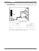
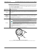
4.2.2MOUNTING CONFIGURATIONS
Ultra Series ISC Cantilever Transducers can be mounted on either the inside or outside of the machine
frame depending on the model type purchased (refer to Figure 9 and Table D). When choosing a mounting
confi
guration, evaluate your options by taking the following points into consideration:
Model type
Safety
Machine Frame orientation
Ease of Assembly
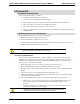
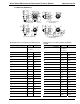
Although Figure shows mounting types for the Ultra Cantilever Transducer, the same types of mounting
configurations and connector locations are also applicable to Ultra ISC Cantilever transducers.
TYPE "S"
MOUNTING
TYPE "PB"
MOUNTING
TYPE "FL"
MOUNTING
STATIONARY/DEAD SHAFT
SENSING ROLL
TYPE "BR"
MOUNTING
MACHINE FRAME MACHINE FRAME
STATIONARY/DEAD SHAFTSTATIONARY/DEAD SHAFTSTATIONARY/DEAD SHAFT
SENSING ROLLSENSING ROLL SENSING ROLL
Figure 9– Types of Mounting Configurations
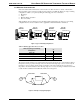
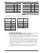
Table D – Mounting Type and Connector Location
The Connector can be located
at:
When using this type of Mounting
Configuration:
End Side
Flange (FL)
X X
Stud (S)
X
Pillow Block (PB)
X
Bearing (BR)
X
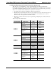
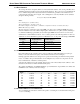
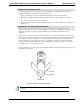
The tension-sensing roll must not be located where the web wrap angle can vary, or the transducer will not
interpret the tension properly as the angle varies. If a variance in the wrap angle occurs, it is sensed by the
transducer as a tension change and the change is indicated on the tension indicator. In cases where it is
impossible to mount the transducer where the wrap angle does not vary, the change in indicated tension that
results should be calculated and if sufficiently small, can be disregarded.
WRAP VARIESWRAP VARIES
PROCESS
OK FOR TENSION SENSING
Figure 10 - Example of Varying Wrap Angles
15