Cleveland Motion Controls INSTRUCTION MANUAL (MAN-70445-0) FOR ULTRA ISC CANTILEVER TRANSDUCER MODELS: CLTEC, CLTSC, CLTECM &CLTSCM REVISION AA
ULTRA SERIES ISC CANTILEVER TRANSDUCER TECHNICAL MANUAL MAN-70445-0 REV AA REVISION HISTORY Rev ECO# Author AA -- WGW Date Description of Change As Released This documentation may not be copied, photocopied, reproduced, translated, or reduced to any electronic medium or machine-readable format without explicit written permission from CLEVELAND MOTION CONTROLS. Copyright © 2007 by ITT, Cleveland Motion Controls Burny/AMC Division 7550 Hub Parkway Cleveland, Ohio 44125-5794 Tele: 216.524.
MAN-70445-0 REV AA ULTRA SERIES ISC CANTILEVER TRANSDUCER TECHNICAL MANUAL WARRANTY AND LIMITATION OF LIABILITY All equipment is sold subject to the mutual agreement that it is warranted by the company to be free from defects of material and workmanship but the company shall not be liable for special, indirect or consequential damages of any kind under this contract or otherwise.
ULTRA SERIES ISC CANTILEVER TRANSDUCER TECHNICAL MANUAL BLANK IV MAN-70445-0 REV AA
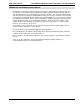
MAN-70445-0 REV AA ULTRA SERIES ISC CANTILEVER TRANSDUCER TECHNICAL MANUAL TABLE OF CONTENTS 1 PRODUCT OVERVIEW .................................................................................................................1 1.1 GENERAL DESCRIPTION ................................................................................................................................... 1 1.2 FEATURES ................................................................................................................
ULTRA SERIES ISC CANTILEVER TRANSDUCER TECHNICAL MANUAL MAN-70445-0 REV AA 4.12 APPLYING FORCE TO TRANSDUCERS ............................................................................................................ 26 4.13 CALIBRATION ACCURACY CONSIDERATIONS ................................................................................................. 26 4.14 FINAL CALIBRATION ...........................................................................................................................
ULTRA SERIES ISC CANTILEVER TRANSDUCER TECHNICAL MANUAL MAN-70445-0 REV AA WARRANTY Cleveland Motion Controls warrants the goods against defects in design, materials and workmanship for the period of 12 months from the date of delivery on the terms detailed in the Cleveland Motion Controls, Inc. Terms and Conditions of Sale, document number AO-90131. Cleveland Motion Controls, Inc. reserves the right to change the content and product specification without notice.
ULTRA SERIES ISC CANTILEVER TRANSDUCER TECHNICAL MANUAL BLANK VIII MAN-70445-0 REV AA
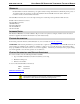
MAN-70445-0 REV AA ULTRA SERIES ISC CANTILEVER TRANSDUCER TECHNICAL MANUAL 1 PRODUCT OVERVIEW 1.1 GENERAL DESCRIPTION The Ultra Series Integrated Signal Conditioning (ISC) Cantilever tension transducer (see Figure 1) outputs a +/- 10 VDC signal for reporting signals from strain gage-based load cells. Ultra ISC transducers include an Integrated Signal Conditioner (ISC) that is coupled directly to the “Ultra” type load cell employing semiconductor strain gages.
ULTRA SERIES ISC CANTILEVER TRANSDUCER TECHNICAL MANUAL MAN-70445-0 REV AA 1.2 FEATURES Ultra ISC load cell features are: Factory Calibration promotes interchangeability Tension controller observation of individual load cell signals provides increased opportunity for advanced diagnostics and calibration.
MAN-70445-0 REV AA ULTRA SERIES ISC CANTILEVER TRANSDUCER TECHNICAL MANUAL 1.5 GENERAL SPECIFICATIONS Item Specification Comments 21.6-26.4 VDC @ 50mA Basic Isolated Amplifier 3.0 VDC FIXED Internally supplied. Calibration Range Min. 0.9 - Max. 9 Multi-turn Gain adjustment provided.
ULTRA SERIES ISC CANTILEVER TRANSDUCER TECHNICAL MANUAL MAN-70445-0 REV AA 1.8 OPERATING CONDITIONS Condition Isolated Signal Conditioning Amplifier Installation category Category III Pollution Pollution Degree 2 Input supply Earth (Ground) referenced Protection Enclosure mounted 1.
MAN-70445-0 REV AA ULTRA SERIES ISC CANTILEVER TRANSDUCER TECHNICAL MANUAL 1.11 SPECIFICATIONS (CANTILEVER TRANSDUCER) Item: Specification: 1T ALUM 1T STEEL 2T STEEL 1.9 lbs. 0.86 kg. 2.7 lb. 1.23 kg 3.7 lb. 1.68 kg 1T ALUM 1T STEEL 2T STEEL 2.9 lbs. 1.32 kg. 3.7 lbs. 1.68 kg 5.3 lbs. Bearing 2.3 lbs. 1.05 kg. 3.1 lbs. 1.41 kg. 4.2 lbs. 1.91 kg. Pillow Block 4.8 lbs 2.18 kg. 5.6 lbs. 2.54 kg. 7.9 lbs. 3.59 kg. Transducer Weight Flange Weight + Mounting Kit 2.
ULTRA SERIES ISC CANTILEVER TRANSDUCER TECHNICAL MANUAL 1.
MAN-70445-0 REV AA ULTRA SERIES ISC CANTILEVER TRANSDUCER TECHNICAL MANUAL 2 PRODUCT COMPONENTS The Ultra Series ISC Cantilever Tension Transducer (see Figure 3 and Figure 4) consists of a housing that contains the amplifier and power supply boards that are coupled directly to an “Ultra” type load cell. There is an M12 connector to send amplified transducer signals into the analog input of a tension controller, PLC, PAC, drive or local I/O.
ULTRA SERIES ISC CANTILEVER TRANSDUCER TECHNICAL MANUAL MAN-70445-0 REV AA 2.1 M12 MATING CONNECTOR The M12 connector used on the Ultra Series ISC amplifier is a four-pin, DC keyed, male connector that mates directly with the molded cordset offered by Cleveland Motion Controls. Table A lists the pin numbers, signal, Function, wire colors and any notes that apply: When mating the connector, align the keying mechanism and pins so that they enter the socket without you having to apply excessive force.
ULTRA SERIES ISC CANTILEVER TRANSDUCER TECHNICAL MANUAL MAN-70445-0 REV AA In environments with severe electromagnetic noise, it may be necessary to route the cables inside metallic conduit. Polarity changes are accommodated by reversing the physical orientation of the transducer, by interchanging the black and white output wires, or by changing the sense parameter settings in the user’s application software. Figure 6 Installation Wiring Diagram 2.
ULTRA SERIES ISC CANTILEVER TRANSDUCER TECHNICAL MANUAL MAN-70445-0 REV AA Table B lists the part numbers and descriptions for these available cordsets (Get from Web marketing): Length Cordset Part Number Connector Orientation Cordset Part Number Connector Orientation 3M X44-33975-010 Straight X44-33976-010 Right-Angle 8M X44-33975-026 Straight X44-33976-026 Right-Angle 16M X44-33975-052 Straight X44-33976-052 Right-Angle 24M X44-33975-078 Straight X44-33976-078 Right-Angle 32M X
ULTRA SERIES ISC CANTILEVER TRANSDUCER TECHNICAL MANUAL MAN-70445-0 REV AA analog signal from an internal op-amp (operational amplifier) buffer stage. The BLK wire has the signal return and the WHT wire is the amplifier output. Resistive loads drawing up to 5 mA of current are allowable. One of the most common ways of reversing the sense of the load cell signal is to invert the mechanical orientation of the load cell body itself.
ULTRA SERIES ISC CANTILEVER TRANSDUCER TECHNICAL MANUAL MAN-70445-0 REV AA 3 PRODUCT APPLICATION The Ultra Series ISC Cantilever Cell Transducer utilizes a twin sensing beam. Conversion from mechanical strain to an electrical signal is accomplished using semiconductor-based, piezoresistive strain gage elements. The Full Wheatstone Bridge configuration provides an electrically balanced output yielding twice the amount of signal swing as half-bridged transducers operated at the same excitation voltage.
MAN-70445-0 REV AA ULTRA SERIES ISC CANTILEVER TRANSDUCER TECHNICAL MANUAL 3.2 SOFTWARE SCALING Figure 8 Software Scaling Here is a simple example of software scaling Command Description Sample (digitize) CLT_CH and store ; Store digitized Cantilever CH. ADD CLT CH_OFSET to CLT_CH parameter ; Cantilever CH_OFSET is the zero correction constant.
ULTRA SERIES ISC CANTILEVER TRANSDUCER TECHNICAL MANUAL MAN-70445-0 REV AA 4 INSTALLATION 4.
ULTRA SERIES ISC CANTILEVER TRANSDUCER TECHNICAL MANUAL MAN-70445-0 REV AA 4.2.2MOUNTING CONFIGURATIONS Ultra Series ISC Cantilever Transducers can be mounted on either the inside or outside of the machine frame depending on the model type purchased (refer to Figure 9 and Table D).
ULTRA SERIES ISC CANTILEVER TRANSDUCER TECHNICAL MANUAL MAN-70445-0 REV AA 4.2.3MOUNTING HARDWARE AND FASTENER TORQUE RECOMMENDATIONS Table E provides you with guidelines to refer to when determining torque values for clean and dry fasteners. Keep in mind, however, that several variables can influence the “optimum” torque to be used in a given situation, and Table E should be used only as a general guide.
ULTRA SERIES ISC CANTILEVER TRANSDUCER TECHNICAL MANUAL MAN-70445-0 REV AA CLTECM-2T CLTSCM-2T Base Stud M16-2 65 Base Bolt (Bearing and Pillow Block) M8-1.25 8 Shaft Adapter 1/4-20 NC 6 Shaft Set Screw M6-1 4 Flange Bolt M12-1.75 18 Mechanisms used for industrial automation can tax even the best threaded fasteners. You can improve the likelihood that bolts and shafts remain secure by using suitable anaerobic “thread lockers” during the final assembly.
ULTRA SERIES ISC CANTILEVER TRANSDUCER TECHNICAL MANUAL MAN-70445-0 REV AA 4.2.4MOUNTING DIMENSIONS L F P O C V L I R (MAX) C A A 45 DEG K K H E (MAX) J J N (B.C.
ULTRA SERIES ISC CANTILEVER TRANSDUCER TECHNICAL MANUAL MAN-70445-0 REV AA T 0.58 0.68 T 14.7 17.3 U 1.63 1.94 U 41.3 49.2 V 1.70 1.02 V 25.9 25.9 W 1.75 1.88 W 44.5 47.7 X - - X - - Y 1/2 1/2 Y M-12 M12 Z (Radius) 1.50 1.70 Z 38.1 43.2 *Maximum shaft diameter 30.
ULTRA SERIES ISC CANTILEVER TRANSDUCER TECHNICAL MANUAL MAN-70445-0 REV AA 4.3.2ROLL BALANCE The sensing roll must be adequately balanced. Understand that the balance of the sensing roll will be more demanding than that typically needed in general rotating machinery. The goal goes beyond just limiting the force to which bearings will be subjected, but rather to minimize the generation of an unintended noise component in the transducer tension signal.
MAN-70445-0 REV AA ULTRA SERIES ISC CANTILEVER TRANSDUCER TECHNICAL MANUAL 4.4 MOUNTING THE TRANSDUCER The mounting surface for the transducer should be flat and true to the web path. Remove any loose paint, rust or scale from the machine frame before mounting. A clean metallic surface helps ensure that the body of the transducer is at frame potential.
ULTRA SERIES ISC CANTILEVER TRANSDUCER TECHNICAL MANUAL MAN-70445-0 REV AA 4.5 MOUNTING THE SENSING ROLL The following steps take into consideration the risk and difficulty of handling large rolls and help to minimize the number of failed attempts at mounting the roll. 1. Before mounting the sensing roll, confirm that the transducer body is securely mounted. 2. Measure the roll shaft diameter, the shaft adapter bore diameter to be sure that they fit properly. 3.
ULTRA SERIES ISC CANTILEVER TRANSDUCER TECHNICAL MANUAL MAN-70445-0 REV AA 4.7 CHECKING THE TRANSDUCER MOUNTING Before preparing to apply force to the transducer(s) and calibrating the tension controller, inspect the load cell to confirm that it is oriented and mounted in accordance to the installation instructions. Common problems include: Failure to mount transducers on flat (machined) surface. Shaft length or roll weight that exceeds allowable limits.
ULTRA SERIES ISC CANTILEVER TRANSDUCER TECHNICAL MANUAL MAN-70445-0 REV AA 4.9 ADJUSTMENT TOOLS (ONLY IF NOT USING NUMERICAL CORRECTION) Using the correct tools simplifies the setup process and necessary adjustments. Keep the following points in mind: The Integrated Signal Conditioning Amplifier utilizes two different potentiometers. The Gain and Zero adjustments are located on the side of the amplifier (under the sticker). The adjustment tool should have dimension on the order of 0.5mm (.
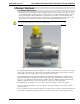
MAN-70445-0 REV AA ULTRA SERIES ISC CANTILEVER TRANSDUCER TECHNICAL MANUAL 4.11 PROPER PRACTICES FOR APPLYING CALIBRATION FORCES Seldom is a transducer oriented such that the calibration can be done by simply hanging a true dead weight from the roll. By generating a tension force that follows the same web path across the roll, you avoid the necessity of making manual (numerical) calculations to correct for the details of different wrap angle, transducer orientation, etc.
ULTRA SERIES ISC CANTILEVER TRANSDUCER TECHNICAL MANUAL MAN-70445-0 REV AA Examples of Force Loss due to Friction at Driven Roll (This figure may not represent the load cell style that you have.) In this example, by rearranging the anchor point and the force location as well as utilizing the idle roll, the frictional losses are minimized. In this example, only a fraction of the test force is transferred to the transducer due to drag from the driven roll. 4.
MAN-70445-0 REV AA ULTRA SERIES ISC CANTILEVER TRANSDUCER TECHNICAL MANUAL Passing a cord over a roll on its way to the transducer inevitably causes some amount of friction. The worst case scenario involves passing the working part of a cord over a roll that doesn’t readily freewheel. A test was conducted to determine the loss on a stationary 4” diameter anodized roll with a 90 degree wrap angle.
ULTRA SERIES ISC CANTILEVER TRANSDUCER TECHNICAL MANUAL MAN-70445-0 REV AA 4.15 EMC CONNECTIONS AND INSTALLATION Compliance with the specified EMC directive for immunity in a heavy industrial environment and emissions in a light industrial environment requires correct installation and wiring of the Ultra ISC Tension Transducer.
ULTRA SERIES ISC CANTILEVER TRANSDUCER TECHNICAL MANUAL MAN-70445-0 REV AA 4.16 CABLE GLANDS Several manufacturers provide cable glands that can be used to ensure the integrity of the EMC requirements when installing this equipment in the enclosure. The objective of the cable gland is to provide a good mechanical entry into the enclosure to protect the cable and also provide an electrical bond the outer shield (screen) of the cable to the enclosure.
ULTRA SERIES ISC CANTILEVER TRANSDUCER TECHNICAL MANUAL MAN-70445-0 REV AA 5 TROUBLESHOOTING Safety should not be an afterthought. Before installing, servicing or calibrating review and follow applicable policies and procedures to ensure worker safety. Machinery must be in a safe state and be aware of any additional hazards that can arise when installing and calibrating higher force transducers.
MAN-70445-0 REV AA ULTRA SERIES ISC CANTILEVER TRANSDUCER TECHNICAL MANUAL 5.1 TRANSDUCER BENCH TESTING Because the strain gage signal conditioning is completely internal to the transducer, it is impractical to directly measure the resistance of the stain gage elements. This complicates the task of bench testing. However, there are measurable indications of the potential functionality. 1. Measure the DC load current powering the ISC.
ULTRA SERIES ISC CANTILEVER TRANSDUCER TECHNICAL MANUAL 6 MANUFACTURERS DECLARATION OF CONFORMITY 32 MAN-70445-0 REV AA