
Instruction Manual

5
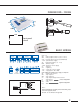
TYPICAL APPLICATION EXAMPLES
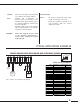
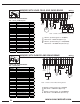
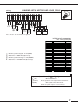
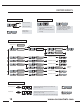
WIRING UNWIND WITH EMAG BRAKE AND ULTRASONIC SENSOR
OPEN LOOP
Com
+24
C1
C2
V+
A
B
V+
Init
Reg
Com
DM
+24
+24 V
AC / DC
EMAG
Brake
Ultrasonic
Sensor
+
-
S
Blue
Bleu
Yellow
Jaune
Brown
Brun
Jumper
NR7
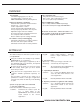
Initial set of parameters
File : Diameter_measurement.prm
DISPLAY Line 1 Set Point
Line 2 Diameter
FUNCTIONS Time Delay Start
Time Delay Stop
Hold
INPUTS Set Point 50
Diameter Filtering 1000
Tachymeter Filtering
OUTPUTS Upper Limit 0
Bottom Limit 10
Power Gain 100
RE GULATION Max Effort 100
P
I
D
Measurement Filtering
Open Loop Gain 100
Closed Loop Gain
Speed Gain
Coeff Speed
Overspeed
Note : all Com / 0V are linked to the ground
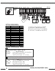
Troubleshooting
Check: All wiring, in particular ensure cable
shields are properly connected
Ensure the parameter settings are in
full accordance with the related
applications tables
Stability: When necessary adjust the parameters
(*) to improve the system stability
Note: Variable PID (coefficients are
proportional to the diameter) is also
available when system stability cannot
be obtained (diameter measurement
must be available).
Detailed features about the Variable
PID are fully available in the Help file
included to the PC software
CAUTION: Ensure the required “Process” (link
to the machine automation) is
active before starting the system
(logic input B)