
Instruction Manual

3
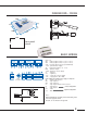
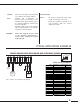
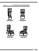
DIMENSIONS - FIXING
166
111
152
38
100
4
Front panel
cutout
156
101
1 - 5 mm
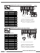
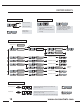
analog
outputs
set
point
tacho /
diameter
measurements
supply
output
control
alarms
logic
inputs
ComCom
A01 A01
ComCom
A02 A02
ComCom
SetPSetP
+10V+10V
ComCom
TCTC
ComCom
DMDM
+24V +24V
S1-
ComCom
S1+
+5V
+5V
ComCom
+24+24
C1C1
C2C2
ALAL-
AL1AL1
AL2AL2
V+V+
A
B
V+
V+
initinit
RegReg
F
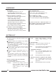
Com : 0 V
A01 : analog output control 1 (-10 to +10 V)
A02 : analog output control 2 (-10 to +10 V)
SetP : set point input (0 to 10V, or potentiometer)
+10V : potentiometer supply
TC : tachometer input (0 to 10 V)
DM : diameter input
+24V : Ultrasonic sensor supply
S1- : Signal (-)
S1+ : Signal (+)
+5V : load cell or sensor supply
+24 : supply (24 V AC or DC)
C1-C2 : PWM output (brakes direct supply) 1.5 Amp max.
AL- : ouptut logic reference
AL1 : logic output 1
AL2 : logic output 2
V+ : logic input voltage remote control
A : logic input 1
B : logic input 2
init : INIT
reg : REG
process configuration
regulator configuration
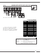
BASIC WIRING
Note :
When grounding the secondary of the transformer, please
refer to the opposite sketch.
All Com / 0V are linked to the ground
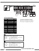
Supply
Com
+24
Secondary
Primary
fuse
3.15A T