
Product Overview
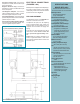

Positive Pressure Only: Connect the
sample line to inlet H; inlet L remains open
to the atmosphere.
Negative Pressure Only: Connect the
sample line to inlet
L; inlet H remains open
to the atmosphere.
Two Negative Samples: Connect the
higher negative sample to inlet
L. Connect
the lower negative sample to inlet H.
Two Positive Samples: Connect the higher
positive sample to inlet
H. Connect the lower
positive sample to inlet L.
One Positive and One Negative Sample
:
Connect the positive sample to inlet H. Con-
nect the negative sample to inlet L.
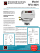
Reference Dimensions in Inches (Millimeters)
Figure 4
SPECIFICATIONS
MODEL RFS-4001
AIR PRESSURE SENSING SWITCH
WITH ADJUSTABLE SET POINT RANGE
Mounting Position:
Mount with the diaphragm
in any vertical plane.
Standard Set Point Range:
• 0.15 ±0.02" wc to 5.0" wc.
Field Adjustable "Operate Range":
• 0.17" wc to 5.0". wc.
Field Adjustable "Release Range":
• 0.14" wc to 4.7". wc.
Approximate Switch Differential:
• Progressive, increasing from
0.05±0.02" wc at minimum set
point to approximately 0.3" wc
at maximum set point.
Measured Media:
Air or combustion by-products
that will not degrade silicone.
Maximum Pressure:
½ psi (0.03 bar).
Operating Temperature Range:
–40 to 180F(–40.0 to 82.2C).
Life:
100,000 cycles minimum at ½ psi
maximum pressure each cycle and
at maximum rated electrical load.
Electrical Rating:
300 VA pilot duty at 115 to 277 VAC;
15 amp noninductive to
277 VAC, 60 Hz.
Contact Arrangement:
• SPDT.
Electrical Connections:
• Screw terminals with cup washers.
Sample Line Connectors:
• Externally threaded
7
⁄16"
UNS 2A thread with nuts and
self-aligning ferrules will ac-
cept 0.25"OD rigid tubing.
Approvals:
UL, CUL.
Shipping Weight:
14.1 oz.
ELECTRICAL CONNECTIONS
(FIGURES 3 & 4)
Before pressure is applied to the diaphragm,
the switch contacts will be in the normally
closed (NC) position. Wire control and alarm
functions as shown in Figure 4.
FIELD ADJUSTMENT
The adjustment range of an RFS-4001 Air
Switch is 0.15±0.02" wc to 5.0"wc.
To adjust the set point, turn the adjusting
screw counterclockwise until motion has
stopped. Next, turn the adjusting screw 5
complete turns clockwise to engage the
spring.
From this point, the next eight turns will be
used for the actual calibration. Each full
turn represents approximately 0.61"
wc.
Please note: To properly calibrate an air
switch, a digital manometer or other mea
-
suring device should be used to confirm the
actual set point.