
Product Overview

Bulletin RFS-4001.00
Cleveland Controls
DIVISION OF UNICONTROL INC.
1111 Brookpark Rd
Cleveland OH 44109
Tel: 216-398-0330
Fax: 216-398-8558
Email:saleshvac@unicontrolinc.com
Web page: http://www.clevelandcontrols.com
Are you
reading a FAX
or a COPY of this
bulletin? DOWNLOAD
the full-color PDF ver
-
sion of this and other
literature at our
website!
Cleveland Controls
Division of UniControl Inc.
APPLICATION
Model RFS-4001 is a general purpose prov-
ing switch designed for HVAC and Energy
Management applications. This switch can
be used to sense positive, negative, or dif
-
ferential air pressure.
GENERAL DESCRIPTION &
OPERATION
The plated housing contains a diaphragm, a
calibration spring, a snap-acting switch and
enclosure cover. The sample line connec
-
tions located on each side of the diaphragm
accept 0.25" metallic tubing via the integral
compression ferrule and nut. Various electri
-
cal connections are available. An enclosure
cover protects the operator from accidental
contact . The enclosure cover accepts a 0.5"
conduit connection.
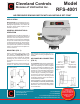
MOUNTING (FIG. 1)
Select a mounting location which is free
from vibration. The Model RFS-4001 must
be mounted with the diaphragm in any verti
-
cal plane in order to maintain the specified
operating set point. Avoid mounting with
the sample line connections in the "up"
position.
The standard model is surface-mounted via
the four
3
⁄16" wide slots on the zinc-plated
strap bracket.The mounting slots are 3-
7
⁄8"
apart. Custom mounting configurations are
available.
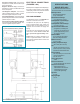
AIR SAMPLING CONNECTION
(FIG. 2)
Model RFS-4001 switches are equipped with
sample line connections situated on either
side of the diaphragm as shown in Figure
2. These connections are suitable for ¼"OD
metallic tubing. Locate the sampling probe a
minimum of 1.5 duct diameters downstream
from the air source. For sample lines up to
10 feet in length, ¼"OD tubing is acceptable.
For lines up to 20 feet,use ¼"ID tubing. For
lines up to 60 feet, use ½" ID tubing. Install
the sampling probe as close to the center of
the airstream as possible.
Refer to Figure 2
to identify the high pres-
sure inlet (H)
and the low pressure inlet
(L). Select one of the five application options
listed below, and connect the sample lines
as recommended.
Figure 1: Mount with the diaphragm in
any vertical plane.
Figure 3
Figure 2
Positive Only
Lower Negative
Higher Positive
Negative Only
Higher Negative
Lower Positive
Model
RFS-4001
AIR PRESSURE SENSING SWITCH WITH ADJUSTABLE SET POINT