
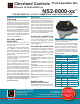
Product Overview

Cleveland Controls
Division of UniControl Inc.
Cleveland Controls
DIVISION OF UNICONTROL INC.
1111 Brookpark Rd
Cleveland OH 44109
Tel: 216-398-0330
Fax: 216-398-8558
Email:saleshvac@unicontrolinc.com
Web page: http://www.clevelandcontrols.com
Are you
reading a FAX
or a COPY of this
bulletin? DOWNLOAD
the full-color PDF ver-
sion of this and other
literature at our
website!
Bulletin LTNS20000xx-04
GENERAL DESCRIPTION &
OPERATION
The NS2™ Switch has a glass-lled poly-
carbonate housing containing a sensing dia-
phragm and an integral snap-acting switch
with three male 90° quick-connect terminals.
The switch can be actuated by a pressure or
vacuum air ow or the differential between
two air ows. The eld adjustable set point
range of the switch is 0.10"w.c. to 10.0"w.c.
Using the switch accessories contained in
this kit, the NS2™ switch can be applied to
a wide variety of residential and light com-
mercial HVAC applications.
SET POINT RANGE &
ADJUSTMENT
Calibration requires a manometer (not
included in the kit) as well as the included
7/
32
" hex wrench.
1. Establish the set point as follows. Refer-
ring to Table 2 in this manual, select the
appropriate spring for the required set point
range. Insert the spring into the center well
of the mounting pan (light gray side of the
switch housing).
2.Insert the black set point adjustment
screw, and rotate it manually until the
threads are engaged.
3. Connect the switch to a manometer. Us-
ing the
7/
32
" hex wrench provided in the kit,
turn the adjustment screw in small incre-
ments until the desired set point is reached.
Turn the screw clockwise to increase the set
point or counterclockwise to decrease the
set point. For precise calibration, conrm
the set point at actual operating temperature
with a manometer. Following precise cali-
bration, if desired, seal the adjusting screw
using Three Bond #TB3015B UV curable
adhesive/sealant. Do not place the switch
in operation without knowing what the
set point is: doing so could create a
hazardous situation.
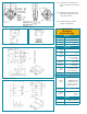
MOUNTING
Using the (2) #6-3/8 mounting screws in-
cluded in the kit, mount via the integral foot
bracket (see Fig. 1) or, via either of the op-
tional brackets (see Figs 4 & 5) included in
the kit. If using one of the optional brackets,
attach it to the switch with the self tapping
screw provided before mounting the switch.
Select a mounting location free from vibra-
tion. Mount with the diaphragm in any verti-
cal plane. Avoid mounting with the sample
line connections directed upward.
ELECTRICAL CONNECTIONS
The snap switch has three ¼" 90° male
quick connect terminals. Before pressure
is applied to the diaphragm, the switch
contacts are in the deactivated position as
shown in Figure 2.
AIR SAMPLING CONNECTION
Integral sample line connectors, located on
both sides of the diaphragm, accept
3/
16
"
ID exible tubing. See Figure 3. The High
or Positive inlet (P1) is black and the Low
or Negative inlet (P2) is gray. Connect the
sample lines as follows:
Positive Pressure Only: Connect the
sample line to P1; P2 remains open to the
atmosphere.
Negative Pressure Only: Connect the
sample line to P2; P1 remains open to the
atmosphere.
Two Negative Samples: Connect higher
negative sample to P2; lower sample to
P1.
Two Positive Samples: Connect higher
positive sample to P1; lower sample to
P2.
One Positive and One Negative: Connect
positive sample to P1; connect negative
sample to P2.
USING A FLOW-
RESTRICTING ORIFICE
Some applcations require a delayed switch-
ing action after set point is reached. The
Field Adjustable Kits
NS2-0000-xx
™
FOR RESIDENTIAL & LIGHT COMMERCIAL HVAC APPLICATIONS
delay is created by inserting an orice plug
into either or both of the sample line con-
nectors to restrict air ow .
Eight orice plugs in four color-coded sizes
are included in the kit, as shown in
Table
3. Note that the measuring device and the
NS2™ air switch must both contain the
same size restricting orice in order to obtain
an accurate measurement of the set point.
More information is available in
Technical
Bulletin 030109-1.
TABLE 1: MODEL SELECTION
NS2-0000-00
Basic model
NS2-0000-01
Bleed hole in Mounting Pan
TABLE 2: SPRING SELECTION
Part No. Color Set Point Range ("wc)
61523 Black 0.10 thru 0.30
61513 Natural 0.30 thru 0.90
61514 Yellow 0.90 thru 2.50
61515 Red 2.50 thru 5.00
61524 Blue 5.00 thru 10.00
TABLE 3: ORIFICE SELECTION
Part No. Color Diameter
61518001 Green 0.010
61518002 Gray 0.016
61518003 Red 0.028
61518004 Blue 0.035