
Product Overview

Cleveland Controls
DIVISION OF UNICONTROL INC.
1111 Brookpark Rd
Cleveland OH 44109
Tel:
216-398-0330
Fax: 216-398-8558
Email:saleshvac@unicontrolinc.com
Web page: http://www.clevelandcontrols.com
Are you
reading a FAX
or a COPY of this
bulletin? DOWNLOAD
the full-color PDF ver
-
sion of this and other
literature at our
website!
Cleveland Controls
Division of UniControl Inc.
DFS221-112.05
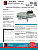
(Figure 1)
Model
DFS–221-112
AIR PRESSURE SENSING SWITCH WITH FIXED SET POINT RANGE
APPLICATION
Model DFS–221–112 is an airflow proving
switch designed for duct heater, oven, and
other HVAC or Energy Management ap-
plications where an open-mounted, nonad
-
justable switch is desirable. It is especially
suitable for surface-mounting in areas where
internal access is limited. It can be used to
sense positive, negative, or differential air
pressure. The DFS–221–112 is equipped
with a convenient barbed sample line con
-
nector that accepts flexible tubing.
GENERAL DESCRIPTION &
OPERATION
The plated housing contains a diaphragm
and a snap-acting SPDT switch. The barbed
sample line connections located on each
side of the diaphragm accept flexible tubing.
The electrical connection consists of male
1/4-inch quick connect terminals.
The SPDT snap action switch operates on
pressure rise of 0.05"w.c.,
+ 0.02" w.c. For
additional application and technical informa
-
tion, please contact the sales office.
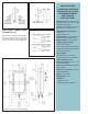
MOUNTING
(FIGURE 1)
Select a mounting location which is free
from vibration. The DFS–221–112 must be
mounted with the diaphragm in any verti
-
cal plane in order to maintain the specified
operating set point. Avoid mounting with the
sample line connections in the "up" position.
Surface mount via the two 3/16" diameter
holes on the zinc-plated strap bracket. The
mounting holes are 3-7/8" apart.
AIR SAMPLING CONNECTION
(FIGURE 2)
The DFS–221–112 is equipped with two 1/4"
slip-on sample line connections, situated on
either side of the diaphragm as shown in
Figure 2. These connections are suitable
for flexible tubing.
Locate the sampling probe a minimum of
1.5 duct diameters downstream from the air
source. Install the sampling
probe as close
to the center of the airstream as possible.
Refer to Figure 2 to identify the high pres
-
sure inlet (H) and the low pressure inlet (L).
Select one of the five application options
listed below, and connect the sample lines
as recommended.
POSITIVE PRESSURE ONLY: Connect the
sample line to inlet H; inlet L remains open
to the atmosphere.
NEGATIVE PRESSURE ONLY: Connect the
sample line to inlet L; inlet H remains open
to the atmosphere.
TWO NEGATIVE SAMPLES: Connect the
higher negative sample to inlet L. Connect
the lower negative sample to inlet H.
TWO POSITIVE SAMPLES: Connect the
higher positive sample to inlet H. Connect
the lower positive sample to inlet L.
ONE POSITIVE AND ONE NEGATIVE
SAMPLE: Connect the positive sample to
inlet H. Connect the negative sample to
inlet L.
Mount with the diaphragm in any vertical
plane.