
Product Overview
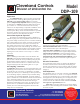

Cleveland Controls
Division of UniControl Inc.
Model
DDP–109
Application
The Model DDP-109 is a general purpose proving switch
designed for HVAC and Energy Management applications. The
DDP-109 provides dual switching action: two separately-
operated, independently-adjustable SPDT snap-acting switches
are mounted on a common foot bracket. Differential pressures
up to 2 inches w.c. can be measured. Because the two snap
switches are set independently, an adjustable “deadband” can be
established for control circuits requiring both high and low
actuation points. Many control and alarm functions are possible:
for instance, monitor two pressure sources and sense the differ-
ential for actuation at two independent set points.
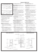
General Description & Operation
Each of the two plated housings contains a diaphragm, a
calibration spring and a snap-acting SPDT switch. There are two
low pressure sample connections (one for each switch assembly),
and a common high pressure sample connection (located on the
foot bracket between the two low pressure connections). All
three sample connections accept ¼" OD metallic tubing via
integral compression ferrule and nut fittings. An enclosure cover
is provided for each switch assembly to guard against accidental
contact with the live switch terminal screws and the set point
adjusting screws. The enclosure covers accept a ½" conduit
connection.
Mounting
Select a mounting location which is free from vibration. The
DDP-109 must be mounted with the diaphragm in any vertical
plane in order to obtain the lowest specified operating set point.
Avoid mounting with the sample line connections in the “up”
position. Surface mount via the two
3
/16" diameter holes in the
integral mounting bracket. The mounting holes are 7" apart.
Air Sampling Connection
The DDP-109 is designed to accept firm-wall sample lines of ¼"
OD tubing by means of ferrule and nut compression connections.
For sample lines of up to 10 feet, ¼" OD tubing is acceptable.
For lines up to 20 feet, use ¼" ID tubing. For lines up to 60 feet,
use ½" ID tubing. Adapters, suitable for slip-on flexible tubing
are available: refer to Bulletin AFS08.01. Locate the sampling
probe a minimum of 1.5 duct diameters downstream from the air
source. Install the sampling probe as close to the center of the
airstream as possible. Refer to the dimensions drawing to
identify the common high pressure inlet “H” and the two low
pressure inlets “L” (on Element A and Element B). For each
element, select one of the following options and connect the
sample lines as recommended.
POSITIVE PRESSURE ONLY: Connect the sample line to
inlet H; inlet L remains open to the atmosphere.
NEGATIVE PRESSURE ONLY: Connect the sample line to
inlet L; inlet H remains open to the atmosphere.
TWO NEGATIVE SAMPLES: Connect the higher negative
sample to inlet L. Connect the lower negative sample to inlet H.
TWO POSITIVE SAMPLES: Connect the higher positive
sample to inlet H. Connect the lower positive sample to inlet L.
ONE POSITIVE AND ONE NEGATIVE SAMPLE: Connect
the positive sample to inlet H. Connect the negative sample to
inlet L.
Electrical Connections
For each element, before pressure is applied to the diaphragm,
the switch contacts will be in the normally closed (NC) posi-
tion.The snap switch has screw-type terminals with cup washers.
For each element, wire alarm and control applications as shown
in Figure 1.
Field Adjustment
The adjustment range of each of the 2 elements of the DDP 109
Air Switch is 0.05 ±.02" w.c. to 2.0" w.c.. To adjust an element’s
set point, turn the adjusting screw counterclockwise until motion
has stopped. Next, turn the adjusting screw 4 complete turns in a
clockwise direction to engage the spring. From this point, the
next ten turns will be used for the actual calibration. Each full
turn represents approximately 0.2" w.c.
Please note: To properly calibrate an air switch, a digital
manometer or other measuring device should be used to confirm
the actual set point.
Bulletin DDP109.00
Cleveland Controls
DIVISION OF UNICONTROL INC.
1111 Brookpark Rd
Cleveland OH 44109
Tel: 216-398-0330
Fax: 216-398-8558
Email:saleshvac@unicontrolinc.com
Web page: http://www.clevelandcontrols.com
Are you
reading a FAX or a
COPY of this bulletin?
DOWNLOAD the full-
color PDF version of
this and other
literature at our
website!