
Product Overview

Bulletin AFSA.02
Bulletin AFSA.02 9/96 draft 2
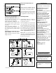
Electrical Connections (see
Figure 3)
Before pressure is applied to the dia-
phragm, the switch contacts will be in
the normally closed (NC) position.
The snap switch has screw top terminals
with cup washers. Wire alarm and con-
trol applications as shown in Figure 4.
Field Adjustment
The adjustment range of an AFS-A Air
Switch is 0.05 to 12.0" w.c., ±.02" w.c.
To adjust the set point:
Turn the adjusting screw counterclock-
wise until motion has stopped. Next,
turn the adjusting screw 4 complete
turns in a clockwise direction to engage
the calibration spring. From this point,
the next ten turns will be used for the
actual calibration. Each full turn rep-
resents approximately 1.2" w.c.
Please note: To properly calibrate a
Air Switch, a digital manometer or other
measuring device should be used to con-
firm the actual set point.
Accessories
• Sample line probes. • Orifice plugs (pulsation
dampeners).
Pressure Conversion Table
1" H
2
O = .0361 lbs./sq. in. or .0735 in. mercury
1" Hg. = .491 lbs./sq. in. or 13.6 in. water
1 psi = 27.7 in. water or 2.036 in. mercury
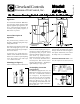
Specifications
Model AFS-A Air Flow Switch
Mounting Position: Mount with the
diaphragm in any vertical plane.
Set Point Range:
0.05 ± 0.02" w.c. to 12.0"w.c. (0.508 mm w.c.
to 304.8 mm w.c.) (0 to 0.43 psi).
Approximate Switching Differential:
Progressive; increases from 0.02±
0.01"w.c. at minimum set point to approxi-
mately 0.8 " w.c. at maximum set point.
Measured Media: Air, or combustion by-
products that will not degrade silicon.
Maximum Pressure: ½ psi
(0.03 bar)
Operating Temperature Range:
-40F to 180F (-40 to 82C)
Life: 100,000 cycles minimum at 1/2 psi
maximum pressure each cycle and at
maximum rated electrical load.
Electrical Rating:
300 VA pilot duty at 115 to 277 VAC,
15 amps noninductive to 277 VAC, 60 Hz.
Contact Arrangement: SPDT
Electrical Connections: Screw-type
terminals with cup washers.
Conduit Opening: 7/8" diameter opening
accepts 1/2" conduit.
Sample Line Connectors:
1/4" - 18 NPT
female (high pressure inlet) 1/8" - 27
NPT female (low pressure inlet)
Sample Line Connections: Connectors
will accept 1/4" OD rigid or semi-rigid
tubing.
Approval: UL, FM, CSA
Shipping Weight: 2 lbs.
remains open to the atmosphere.
NEGATIVE PRESSURE ONLY: Con-
nect the sample line to inlet L; inlet H
remains open to the atmosphere.
TWO NEGATIVE SAMPLES: Con-
nect the higher negative sample to inlet
L. Connect the lower negative sample
to inlet H.
TWO POSITIVE SAMPLES: Con-
nect the higher positive sample to inlet
H. Connect the lower positive sample
to inlet L.
ONE POSITIVE AND ONE NEGA-
TIVE SAMPLE: Connect the positive
sample to inlet H. Connect the negative
sample to inlet L.
(Figure 4)
AFS-A Sensing Switches are manufactured by
Cleveland Controls Div. of UniControl Inc.