
Product Overview

Air Pressure Sensing Switch with Adjustable Set Point Range
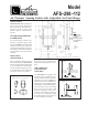
Reference Dimensions in Inches (Millimeters)
APPLICATION
Model AFS–298–112 is a general pur-
pose proving switch designed for
HVAC and Energy Management ap-
plications. It may be used to sense
positive, negative, or differential air
pressure.
GENERAL DESCRIPTION
& OPERATION
The plated housing contains a dia-
phragm, a calibration spring, and a
snap-acting SPDT switch. The barbed
sample line connections located on
each side of the diaphragm accept flex-
ible tubing. The electrical connection
consists of male ¼-inch quick connect
terminals.
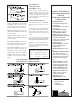
MOUNTING
(SEE FIGURE 1)
Select a mounting location which is
free from vibration. The AFS–298–112
must be mounted with the diaphragm
in any vertical plane in order to main-
tain the specified operating set point.
Avoid mounting with the sample line
connections in the "up" position.
Surface mount via the two
3
/16" diam-
eter holes on the zinc-plated strap
bracket.The mounting holes are 3-
7
/8"
apart.
AIR SAMPLING
CONNECTION
(FIGURE 2)
The AFS–298–112 is equipped with
two barbed, slip-on sample line con-
nections, situated on either side of the
diaphragm as shown in Figure 2.
These connections are suitable for flex-
ible tubing. Locate the sampling probe
a minimum of 1.5 duct diameters down-
stream from the air source. For sample
lines up to 10 feet in length, ¼"OD
tubing is acceptable. For lines up to
20 feet,use ¼"ID tubing. For lines up
to 60 feet, use ½" ID tubing. Install
the sampling probe as close to the cen-
ter of the airstream as possible.
Model
AFS–298–112
Figure 1: Mount with the
diaphragm in any vertical plane.
Figure 3
Note:
Adhesive for
bonding snap
switch to
housing applied
to underside of
housing.
Figure 2
Positive Only
Lower Negative
Higher Positive
Negative Only
Higher Negative
Lower Positive