
Product Overview

Bulletin AFS–275.00
2
SPECIFICATIONS
MODEL AFS-275
AIR PRESSURE SENSING
SWITCH
WITH ADJUSTABLE SET
POINT RANGE
Mounting Position:
Mount with the diaphragm in any
vertical plane.
Set Point Range: 0.05 ±0.02"w.c.
to 2.0" w.c.
Field Adjustable "Operate
Range": 0.07"w.c. to 2.0."w.c
Field Adjustable "Release
Range": 0.04"w.c. to 1.9"w.c.
Approximate Switch Differential:
Progressive, increasing from
0.02±0.01"w.c. at minimum set point
to approximately 0.1"w.c. at
maximum set point.
Measured Media: Air or combustion
by-products that will not degrade
silicone.
Maximum Pressure: ½ psi (0.03
bar)
Operating Temperature Range:
–40 to 180F (–40.0 to 82.2C)
Life: 100,000 cycles minimum at ½
psi maximum pressure each cycle
and at maximum rated electrical
load.
Electrical Rating: 300 VA pilot
duty at 115 to 277 VAC; 15 amp
noninductive to 277 VAC, 60 Hz.
Contact Arrangement: SPDT
Electrical Connections: Male,
¼", 90° quick-connect terminals
Sample Line Connectors: Two
¼" slip-on connectors, suitable for
flexible tubing
Approvals: UL, CSA, CE
Shipping Weight: 1.2 lbs
Accessories:
• Sample line probes
• Orifice plugs
(pulsation dampers)
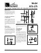
Location of Sample Lines for Typical Applications
Refer to Figure 2 to identify the high
pressure inlet (H) and the low pres-
sure inlet (L). Select one of the five ap-
plication options listed below, and con-
nect the sample lines as recommended.
Positive pressure only: Connect the
sample line to inlet H; inlet L remains open
to the atmosphere.
Negative pressure only: Connect the
sample line to inlet L; inlet H remains open
to the atmosphere.
Two Negative Samples: Connect the
higher negative sample to inlet L. Connect
the lower negative sample to inlet H.
Two Positive Samples: Connect the
higher positive sample to inlet H. Con-
nect the lower positive sample to inlet L.
One Positive and One Negative
Sample: Connect the positive sample to
inlet H. Connect the negative sample to
inlet L.
ELECTRICAL
CONNECTIONS
(FIGURES 3 & 4)
Before pressure is applied to the dia-
phragm, the switch contacts will be in the
normally closed (NC) position. The snap
switch has 90º male quick connect termi-
nals. Wire control and alarm functions as
shown in Figure 4.
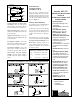
FIELD ADJUSTMENT
The adjustment range of an AFS–275 Air
Switch is 0.05±0.02"w.c. to 2.0" w.c.
To adjust the set point, turn the adjusting
screw counterclockwise until motion has
stopped. Next, turn the adjusting screw 4
complete turns clockwise to engage the
spring.
From this point, the next ten turns will be
used for the actual calibration. Each full
turn represents approximately 0.2" w.c.
Please note: To properly calibrate an air
switch, a digital manometer or other mea-
suring device should be used to confirm
the actual set point.
PRESSURE CONVERSION TABLE
1" H
2
O = 0.0361 lbs/sq. in.= 0.0735 in. Hg
1 in Hg = 0.491 lbs/sq. in = 13.6 in H
2
O
1 psi = 27.7 in. H
2
O = 2.036 in. Hg
Figure 4