
Product Overview

Bulletin AFS 275.00
Air Pressure Sensing Switch with Adjustable Set Point Range
Dimensions in Inches
(Millimeters)
APPLICATION
Model AFS–275 is a general purpose
proving switch designed for HVAC
and Energy Management applications.
It may be used to sense positive, nega-
tive, or differential air pressure.
GENERAL DESCRIPTION
& OPERATION
The plated housing contains a dia-
phragm, a calibration spring, and a
snap-acting SPDT switch. The sample
line connections located on each side
of the diaphragm accept flexible tub-
ing. The electrical connection consists
of male ¼-inch quick connect termi-
nals.
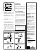
MOUNTING
(SEE FIGURE 1)
Select a mounting location which is
free from vibration. The AFS–275 must
be mounted with the diaphragm in any
vertical plane in order to maintain the
specified operating set point. Avoid
mounting with the sample line connec-
tions in the "up" position.
Surface mount via the two
3
/16" diam-
eter holes on the zinc-plated strap
bracket.The mounting holes are 3-
7
/8"
apart.
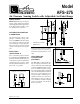
AIR SAMPLING
CONNECTION
(FIGURE 2)
The AFS–275 is equipped with two
slip-on sample line connections, situ-
ated on either side of the diaphragm
as shown in Figure 2. These connec-
tions are suitable for flexible tubing.
Locate the sampling probe a minimum
of 1.5 duct diameters downstream from
the air source. For sample lines up to
10 feet in length, ¼"OD tubing is ac-
ceptable. For lines up to 20 feet,use
¼"ID tubing. For lines up to 60 feet,
use ½" ID tubing. Install the sampling
probe as close to the center of the air
stream as possible.
Model
AFS–275
Figure 2
Figure 1: Mount with the
diaphragm in any vertical plane.
Figure 3
Positive Only
Lower Negative
Higher Positive
Negative Only
Higher Negative
Lower Positive