
Product Overview
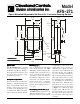

High
Pressure
:
Positive Only
Lower Negative
Higher Positive
Inlet H
Low
Pressure
:
Negative Only
Higher Negative
Lower Positive
Inlet L
Mount with the diaphragm in any
vertical plane to obtain the lowest
specified operating set point.
SpecificationsSpecifications
SpecificationsSpecifications
Specifications
Model AFS-271 Air Flow Switch
Mounting Position: Mount with the
diaphragm in any vertical plane.
Set Point Range: 0.05 ± 0.02" w.c. to
2.0"w.c.
Field Adjustable “Operate Range”:
0.05"w.c. to 2.0" w.c.
Field Adjustable “Release Range”:
0.02"w.c. to 1.9" w.c.
Approximate Switching Differential:
Progressive, increasing from 0.02± 0.01
"w.c. at minimum set point to approxi-
mately 0.1" w.c. at maximum set point.
Measured Media: Air, or combustion
by-products that will not degrade silicon.
Maximum Pressure: ½ psi
(0.03 bar)
Operating Temperature Range:
-40F to 180F (-40 to 82C)
Life: 100,000 cycles minimum at 1/2 psi
maximum pressure each cycle and at
maximum rated electrical load.
Electrical Rating:
300 VA pilot duty at 115 to 277 VAC,
15 amps noninductive to 277 VAC,
60 Hz.
Contact Arrangement: SPDT
Electrical Connections: ¼" 90–degree
quick connects.
Sample Line Connectors: Male,
externally threaded
7
/16" 24 UNS 2A
thread, complete with nuts and self-
aligning ferrules.
Sample Line Connections: Connectors
will accept ¼" OD rigid or semi-rigid
tubing.
Approval: UL, FM, CSA
Shipping Weight: 1.2 lbs.
Accessories
• P/N 18311 Slip-on ¼" OD Tubing Adapter, suitable
for slipping on flexible plastic tubing. • Sample line
probes. • Orifice plugs (pulsation dampers).
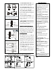
Location of Sample Lines for Typical Applications
N O
ALARM
CONTROL
N O
ALARM
CONTROL
To prove excessive air flow or pressure:
To prove insufficient air flow or pressure:
(
Figure 4
)
(
Figure3
)
POSITIVE PRESSURE ONLY: Con-
nect the sample line to inlet H; inlet L
remains open to the atmosphere.
NEGATIVE PRESSURE ONLY: Con-
nect the sample line to inlet L; inlet H
remains open to the atmosphere.
TWO NEGATIVE SAMPLES: Con-
nect the higher negative sample to in-
let L. Connect the lower negative
sample to inlet H.
TWO POSITIVE SAMPLES: Con-
nect the higher positive sample to in-
let H. Connect the lower positive
sample to inlet L.
ONE POSITIVE AND ONE NEGA-
TIVE SAMPLE: Connect the posi-
tive sample to inlet H. Connect the
negative sample to inlet L.
Electrical Connections (FElectrical Connections (F
Electrical Connections (FElectrical Connections (F
Electrical Connections (F
ig. 3)ig. 3)
ig. 3)ig. 3)
ig. 3)
Before pressure is applied to the dia-
phragm, the switch contacts will be in
the normally closed (NC) position. The
snap switch has ¼" 90–degree quick
connect terminals. Wire alarm and con-
trol applications as shown in Fig.4.
FF
FF
F
ield Adjustmentield Adjustment
ield Adjustmentield Adjustment
ield Adjustment
The adjustment range of an AFS-271
Air Switch is 0.05 ±.02" w.c. to 2.0"
w.c. To adjust the set point, turn the
adjusting screw counterclockwise un-
til motion has stopped. Next, turn the
adjusting screw 4 complete turns in
a clockwise direction to engage the
spring. From this point, the next ten
turns will be used for the actual cali-
bration. Each full turn represents
approximately 0.2" w.c.
Please note: To properly cali-
brate a Air Switch, a digital manometer
or other measuring device should be
used to confirm the actual set point.
LOW
HIGH