
Product Overview
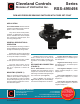

Bulletin RSS495/498.01
SPECIFICATIONS
SERIES RSS-495/498 AIR
PRESSURE SENSING
SWITCHES
Mounting Position:
Mount with the diaphragm in any vertical
plane to obtain specified operating set point.
Set Point Range:
Factory calibrated to meet customer design
specification, from 0.12 + 0.05"w.c. to 4.0" w.c.
Approximate Switching Differential:
.10 ± 0.02"w.c.
Measured Media:
Air, or combustion by-products that will
not degrade EPDM and Thermoplastic.
Operating Temperature Range:
-40F to 190F (-40 to 88C).
Maximum Pressure: 1 psi (0.06 bar).
Life: 100,000 cycles minimum.
Electrical Rating:
5 amp noninductive 120 to 277 V AC
1 amp pilot duty (120 va) at 120 V AC
Contact Arrangement:
spdt, spst/no or spst/nc logic.
Electrical Connections:
Male, 1/4" and/or 3/16" “quick-con-
nect” spade terminals.
Sample Line Connections:
Standard barbed fittings will accept ¼"
ID or 3/8" ID flexible, slip-on tubing.
Approval:
UL, CSA, CE, NRTL, & Aust. Gas Assoc.
Shipping Weight: 0.25 lbs.
Options:
• Bleed hole.
• Custom mounting brackets.
• Flow restriction orifice
• Snap switch positions.
• Sample line connector positions.
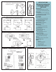
Fig. 2
Nominal Dimensions in Inches (Millimeters)
Fig. 3: Without pressure applied to the diaphragm,
switch contacts are in the position shown.
Figure 4
Figure 5
Fig. 1: Mount with the diaphragm in any
vertical plane. Sample line connections
should not point up.