
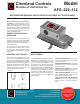
Product Overview

SPECIFICATIONS
MODEL AFS-222-112 AIR
PRESSURE SENSING
SWITCH WITH ADJUSTABLE
SET POINT RANGE
Mounting Position: Mount with the
diaphragm in any vertical plane.
Set Point Range: 0.05 ± 0.02" w.c. to
12.0"w.c.
Field Adjustable “Operate Range”:
0.07"w.c. to 12.0" w.c.
Field Adjustable “Release Range”:
0.04"w.c. to 11.2" w.c.
Approximate Switching Differential:
Progressive, increasing from 0.02 ±
0.01"w
.c. at minimum set point to approxi-
mately 0.8 " w.c. at maximum set point.
Measured Media: Air, or combustion by-
products that will not degrade silicone.
Maximum Pressure: ½ psi (0.03 bar).
Operating T
emperature Range:
-40F to 180F (-40 to 82C).
Life: 100,000 cycles minimum at 1/2 psi
maximum pressure each cycle and at
maximum rated electrical load.
Electrical Rating:
300 VA pilot duty at 115 to 277 VAC,
15 amps noninductive to 277 VAC, 60 Hz.
Contact Arrangement: SPDT.
Electrical Connections: Screw-type
terminals with cup washers.
Conduit
Opening: 7/8" diameter opening
accepts ½" conduit.
Sample Line Connectors: Two barbed
¼" connectors will accept fl
exible tubing.
Sample Line Connections: Two barbed
¼" connectors will accept flexible tubing.
Approval: UL, FM, CSA, CE
Shipping Weight: 1.2 lbs.
Accessories:
• Sample line probes.
• Orifice plugs (pulsation dampers).
ELECTRICAL
CONNECTIONS (SEE
FIGURE 3)
Before pressure is applied to the diaphragm,
the switch contacts will be in the normally
closed (NC) position. The snap switch has
screw top terminals with cup washers. Wire
alarm and control applications as shown in
Figure 4.
FIELD ADJUSTMENT
The adjustment range of an AFS-222-112
Air Switch is 0.05 ±.02" w.c. to 12.0" w.c.
To adjust the set point, t urn the adjusting
screw counterclockwise until motion has
stopped. Next, turn the adjusting screw
4 complete turns in a clockwise direction
to engage the spring. From this point, the
next ten turns will be used for the actual
calibration. Each full turn represents ap-
proximately 1.2" w.c.
Please note: To properly calibrate an air
switch, a digital manometer or other mea-
suring device should be used to confirm the
actual set point.
(Figure 4)
(Figure 3)
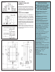
(Figure 2)
Nominal Dimensions in Inches (Millimeters)