
Product Overview

Cleveland Controls
Division of UniControl Inc.
Bulletin LTAFS222112-02
Cleveland Controls
DIVISION OF UNICONTROL INC.
1111 Brookpark Rd
Cleveland OH 44109
Tel: 216-398-0330
Fax: 216-398-8558
Email:saleshvac@unicontrolinc.com
Web page:
http://www.clevelandcontrols.com
Are you
reading a FAX
or a COPY of this
bulletin? DOWNLOAD
the full-color PDF ver-
sion of this and other
literature at our
website!
APPLICATION
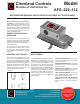
Model AFS-222-112 Air Pressure Sens-
ing Switch is a general purpose proving
switch designed for HVAC and Energy
Management applications. It may be used
to sense positive, negative, or differential air
pressure. The AFS-222-112 is equipped with
convenient barbed sample line connectors
that accept flexible tubing.
GENERAL DESCRIPTION &
OPERATION
The plated housing contains a diaphragm, a
calibration spring and a snap-acting SPDT
switch.The barbed sample line connections
located on each side of the diaphragm ac-
cept flexible tubing.
An enclosure cover guards against acci-
dental contact with the live switch terminal
screws and the set point adjusting screw.
The enclosure cover will accept a ½" conduit
connection.
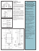
MOUNTING (SEE FIGURE 1)
Select a mounting location which is free
from vibration. The AFS-222-112 must be
mounted with the diaphragm in any vertical
plane in order to obtain the lowest specified
operating set point. Avoid mounting with the
sample line connections in the "up" position.
Surface mount via the two 3/16" diameter
holes in the integral mounting bracket. The
mounting holes are 3-7/8" apart.
(Figure 1)
Th
e AFS-222-112 is designed to accept flex-
ible tubing
by means of barbed 1/4" slip-on
connections. For sample lines of up to 10
feet, ¼” OD tubing is acceptable. For lines
up to 20 feet, use ¼” ID tubing. For lines up
to 60 feet, use ½” ID tubing. Locate the sam-
pling probe a minimum of 1.5 duct diameters
downstream from the air source. Install the
sampling probe as close to the center of the
airstream as possible. Refer to Figure 2 to
identify the high pressure inlet (H) and the
low pressure inlet (L). Connect the sample
lines as follows:
POSITIVE PRESSURE ONLY: Connect the
sample line to inlet H; inlet L remains open
to the atmosphere.
NE
GATIVE PRESSURE ONLY: Connect the
sample line to inlet L; inlet H remains open
to the atmosphere.
TWO NEGATIVE SAMPLES: Connect the
higher negative sample to inlet L. Connect
the lower negative sample to inlet H.
TW
O POSITIVE SAMPLES: Connect the
higher positive sample to inlet H. Connect
the lower positive sample to inlet L.
ONE POSITIVE AND ONE NEGATIVE
SAMPLE: Connect the positive sample to
inlet H. Connect the negative sample to
inlet L.
Model
AFS–222–112
AIR PRESSURE SENSING SWITCH WITH ADJUSTABLE SET POINT RANGE
AIR SAMPLING CONNECTION
(SEE FIGURE 2)