
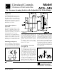
Product Overview

Bulletin AFS145.04 2
Specifications
Model AFS-145 Air Flow Switch
Mounting Position: Mount with the dia-
phragm in any vertical plane.
Set Point Range:
0.05 ± 0.02" w.c. to 12.0"w.c. (0.508 mm
w.c. to 304.8 mm w.c.) (0 to 0.43 psi).
Approximate Switching Differential:
Progressive; increases from 0.02±
0.01"w.c. at minimum set point to approxi-
mately 0.8 " w.c. at maximum set point.
Measured Media: Air, or combustion by-
products that will not degrade silicone.
Maximum Pressure:
½ psi (0.03 bar)
Operating Temperature Range:
-40F to 180F (-40 to 82C)
Life: 100,000 cycles minimum at ½ psi
maximum pressure each cycle and at
maximum rated electrical load.
Electrical Rating:
300 VA pilot duty at 115 to 277 VAC,
15 amps noninductive to 277 VAC, 60 Hz.
Contact Arrangement: SPDT
Electrical Connections: Screw-type ter-
minals with cup washers.
Conduit Opening:
7
/8" diameter open-
ing accepts ½" conduit.
Sample Line Connectors:
1/8" - 27
NPT female connectors (2)
Sample Line Connections: Connectors
will accept ¼" OD rigid or semi-rigid tub-
ing.
Approval: UL, FM, CSA, CE
Shipping Weight: 1.2 lbs.
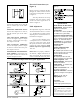
(Figure 3)
Electrical Connections (see
Figure 3)
Before pressure is applied to the dia-
phragm, the switch contacts will be
in the deactivated position as shown
in Figure 3.
The snap switch has screw top
terminals with cup washers. Wire
alarm and control applications as
shown in Figure 4.
Field Adjustment
The adjustment range of an AFS-145
Air Switch is 0.05 ±.02" w.c. to 12.0"
w.c.. To adjust the set point, turn the
adjusting screw counterclockwise un-
til motion has stopped.
Next, turn the adjusting screw
4 complete turns in a clockwise di-
rection to engage the spring. From
this point, the next ten turns will be
used for the actual calibration. Each
full turn represents approximately
1.2" w.c.
Please note: To properly calibrate a
Air Switch, a digital manometer or
other measuring device should be
used to confirm the actual set point.
AFS-145 Sensing Switches are manufactured
by Cleveland Controls Div. of UniControl Inc.
(Figure 4)
Location of Sample Lines for Typical Applications
Accessories
• Sample line probes.
• Orifice plugs (pulsation dampers).
Pressure Conversion Table
1" H
2
O = 0.0361 lbs./sq. in. or 0.0735 in.
mercury
1" Hg. = 0.491 lbs./sq. in. or 13.6 in. water
1 psi = 27.7 in. water or 2.036 in. mercury
POSITIVE PRESSURE ONLY:
Connect the sample line to inlet H;
inlet L remains open to the atmo-
sphere.
NEGATIVE PRESSURE ONLY:
Connect the sample line to inlet L;
inlet H remains open to the atmo-
sphere.
TWO NEGATIVE SAMPLES:
Connect the higher negative sample
to inlet L. Connect the lower nega-
tive sample to inlet H.
TWO POSITIVE SAMPLES:
Connect the higher positive sample
to inlet H. Connect the lower posi-
tive sample to inlet L.
ONE POSITIVE AND ONE NEGA-
TIVE SAMPLE: Connect the posi-
tive sample to inlet H. Connect the
negative sample to inlet L.