
Product Overview

Bulletin AFS145.04 1
Distributed by:
Cleveland Controls
Division of UniControl Inc.
111Brookpark Road • Cleveland OH 44109
TEL: (216) 398-0330 • FAX: (216) 398-8558
Model
AFS–145
Air Pressure Sensing Switch with Adjustable Set Point Range
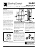
Dimensions in Inches
(Millimeters)
Application
The Model AFS-145 is a general pur-
pose proving switch designed for
package burner, furnace, fuel-burning
equipment, HVAC and other Energy
Management applications. It may be
used to sense positive, negative, or
differential air pressure.
General Description &
Operation
The plated housing contains a dia-
phragm, a calibration spring and a
snap-acting SPDT
switch.The sample
connections located on each side of
the diaphragm accept
1
/8" pipe.
An enclosure cover guards against ac-
cidental contact with the live switch
terminal screws and the set point ad-
justing screw. The enclosure cover
will accept a ½" conduit connection.
Mounting (see Figure 1)
Select a mounting location which is
free from vibration. The AFS-145
must be mounted with the diaphragm
Cleveland Controls
Division of UniControl Inc.
(Figure 2)(Figure 1)
in any vertical plane in order to ob-
tain the lowest specified operating set
point. Avoid mounting with the
sample line connections in the "up"
position. Surface mount via the two
3
/16" diameter holes in the integral
mounting bracket. The mounting
holes are 3-
7
/8" apart.
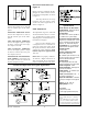
Air Sampling Connection
(see Figure 2)
The AFS-145 is equipped with two
1
/8" – 27 NPT female connectors. For
sample lines of up to 10 feet,
1
/8" pipe
is acceptable. For lines up to 20 feet,
use ¼" pipe. For lines up to 60 feet,
use ½" pipe. For each right angle
bend, add 4 feet to the computed
sample line length to determine cor-
rect pipe size.For sample lines of up
to 10 feet, ¼" OD tubing is accept-
able. For lines up to 20 feet, use ¼"
ID tubing. For lines up to 60 feet, use
½" ID tubing. Locate the sampling
probe a minimum of 1-½ duct diam-
eters downstream from the air source.
Install the sampling probe as close to
the center of the airstream as possible.
Refer to Figure 2 to identify the high
pressure inlet (H) and the low pres-
sure inlet (L). Select one of the five
application options listed below (on
page 2), and connect the sample lines
as recommended.