
Installation Instructions


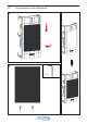


75
PE In
L1 In
N In
L1 Trafo Out
Blauw
Bruin
Gr/Gl
Zwart
P1
P2
S
Zwart
11
11
11
13
9
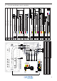
4.5/6/9 kW: 11; Voeding 1x 400 VAC
11: Voeding, 3 x 2.5, 230 VAC
11a: Voeding, 3 x 2.5, 230 VAC
Kies de juiste P1/voeding die bij uw generator zit en volg de instructies.
L3 In
Grijs
11
L2 In
Zwart
11
PE In (2)
L1 In (1)
N In (1)
Blauw
Bruin
Gr/Gl
P1
S
Zwart
11
11
11a
13
4.5/6 kW: Voeding 2x 230 VAC
Gr/Gl
16
L2 In (2)
Bruin
11a
N In (2)
Blauw
11a
4
5
1
2
3
5
1
2
3
PE In (1 )
Gr/Gl
11
N Trafo Out
Bruin
9
1
2
11.5 V 0.8A InB
11.5 V 0.8A InA
11.5 V 8A In
Rood
Groen
Zwart
P3
8
8
8
11.5 V 8A In
Bruin
8
11.5 V 0.8A InA
Oranje
8
11.5 V 0.8A InB
Geel
8
1
2
3
4
5
6
11: Voeding, 3/5 x 2.5, 230/400 VAC
PE In
L1 In
N In
Blauw
Bruin
Gr/Gl
P1
S
Zwart
11
11
11
13
3 kW: 11; Voeding 1x 230 VAC
Grijs
Zwart
5
1
3
11: Voeding, 3/5 x 2.5, 230/400 VAC
Afdoppen
Afdoppen
3
3
1
3
5
5
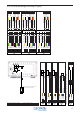
11.5V 0.8A O ut A
11.5V 8A Out
11.5 0.8A Out B
Rd/Bl
Grijs
Bruin
P4
1
1
2
GND 8A Out
Blauw
2
1
2
GND 0.8A O ut B
Gr/Rz
1
3
5
6
Frangrance N
Brug
Brug
GND 0.8 Out A
Waterlevel Max
Heat OK
Waterl evel M in
Heat3 On
Heat 1 On
He at On G ND
Fragrance
Heat2 On
2
1
7
8
1011
13
14
18
19
20
Zwart
Geel
Blauw
Groen
Paars
Zwart
Zwart
Wit
Rood
Roze
Bruin
Blauw
P6
P7
1
1
1
1
1
1
1
1
1
SZwart
13
10
Drain
3
Gr/Gl
2
P9
PE In
Gr/Gl
16
Verw.
Gr/Gl
4
Gr/Gl
7
Verw.
Gr/Gl
5
Kete l
Verw.
Gr/Gl
6
Drain 9kWBlauw
15
Drain 9kWBruin
15
Fragrance NOBruin
10
6
5
4
SZwart
13
3
2
1
Heat3, NBlauw
P8
Heat1, NBlauw
4
6
Heat3, LBruin
6
Heat2, LBruin
5
Heat1, LBruin
4
6
5
4
Heat2, NBlauw
5
3
2
1
1
2
3
4
5
Watersensor Ref In
Watersensor Min In
Zwart
Grijs
P5
12
12
Watersensor Max In
Bruin
12
2
1
3