
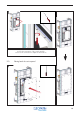
Installation Instructions


153
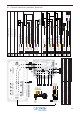
PE In
L1 In
N In
L1 Trafo Out
Blue
Brown
Gr/Ye
Black
P1
P2
S
Black
11
11
11
13
9
4.5/6/9 kW: 11; Power 1x 400 VAC
11:
Power, 3 x 2.5, 230 VAC
11a:
Power, 3 x 2.5, 230 VAC
Choose the right P1/power according to your generator and follow the instructions.
L3 In
Grey
11
L2 In
Black
11
PE In (2)
L1 In (1)
N In (1)
Blauw
Brown
Gr/Ye
P1
S
Zwart
11
11
11a
13
4.5/6 kW: Power 2x 230 VAC
Gr/Ye
16
L2 In (2)
Brown
11a
N In (2)
Blue
11a
4
5
1
2
3
5
1
2
3
PE In (1 )
Gr/Ye
11
N Trafo Out
Brown
9
1
2
11.5 V 0.8A InB
11.5 V 0.8A InA
11.5 V 8A In
Red
Green
Black
P3
8
8
8
11.5 V 8A In
Brown
8
11.5 V 0.8A InA
Orange
8
11.5 V 0.8A InB
Yellow
8
1
2
3
4
5
6
11: Power, 3/5 x 2.5, 230/400 VAC
PE In
L1 In
N In
Blue
Brown
Gr/Ye
P1
S
Black
11
11
11
13
3 kW: 11; Power 1x 230 VAC
Grey
Black
5
1
3
11: Power, 3/5 x 2.5, 230/400 VAC
Capping
Capping
3
3
1
3
5
5
11.5V 0.8A O ut A
11.5V 8A Out
11.5 0.8A Out B
Rd/Bl
Grey
Brown
P4
1
1
2
GND 8A Out
Blue
2
1
2
GND 0.8A O ut B
Gr/Pi
1
3
5
6
Frangrance N
Bridge
Bridge
GND 0.8 Out A
Waterlevel Max
Heat OK
Waterl evel M in
Heat3 On
Heat 1 On
He at On G ND
Fragrance
Heat2 On
2
1
7
8
1011
13
14
18
19
20
Black
Yellow
Blue
Green
Purple
Black
Black
White
Red
Pink
Brown
Blue
P6
P7
1
1
1
1
1
1
1
1
1
SBlack
13
10
Drain
3
Gr/Ye
2
P9
PE In
Gr/Ye
16
Verw.
Gr/Ye
4
Gr/Ye
7
Verw.
Gr/Ye
5
Kete l
Verw.
Gr/Ye
6
Drain 9kWBlue
15
Drain 9kWBrown
15
Fragrance NOBrown
10
6
5
4
SBlack
13
3
2
1
Heat3, NBlue
P8
Heat1, NBlue
4
6
Heat3, LBrown
6
Heat2, LBrown
5
Heat1, LBrown
4
6
5
4
Heat2, NBlue
5
3
2
1
1
2
3
4
5
Watersensor Ref In
Watersensor Min In
Black
Grey
P5
12
12
Watersensor Max In
Brown
12
2
1
3