
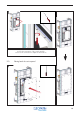
Installation Instructions


152
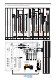
38 Overview connections control box, power box
C4
C6
C3C2C1 C5
C7C8C9
C10
P4
P1
P7
Yellow
Green
Orange
Red
Brown
Black
Black
Brown
1
2
3
4
5
6
7
8
Brown
Orange
Green
Purple
Black
Red
Yellow
Blue
1: Comm. cable, 12x 0.5, 11.8 VDC
2: Power, 2x 0.75, 11.8 VDC
3: Water inlet valve, 2x0.75, 11.5 VDC
4: Heating element 1, 3x 2.5, 230 VAC
5: Heating element 2, 3x 2.5, 230 VAC
8: Power, 6x 0.5, 11.5 VAC
9: Power Transformator, 2x 0.75, 230AC
10: Fragrance pump, 2x 0.75, 230 VAC
12: Water level sensor, 3x 0.75, 11.8 VAC
11: Power, 3/5 x 2.5, 230/400 VAC
6: Heating element 3, 3x 2.5, 230 VAC
13: Power, 1x 0.75
P3P2
P8
9
Trafo
P5P6
C11
14
7: Earth 1x 2.5 14: Connector, 8x 0.5, 11.8 VDC
4
5
6
7
3 2 1
13
10
11
12
8
15
15: Drain 9kW, 3x 0.75, 220 V
11.5V 0.8A Out B
1 2 3 4 5 6 7 8 9
Heat OK
Waterlevel Min
GND 0.8A A
5 VDC
1 Wire TLL A
GND
Fragra nc e
12 11 10 9 8 7 6 5 4 3 2 1
12 11 10 9 8 7 6 5 4 3 2 1
1 2
Purple
C7
C8
C10
Grey
Blue
Red
White
C4
C5
C6
Pink
Green
Blue
C1
C2
C3
1
1
1
14
14
14
1
1
1 2 3 4
C11
GND 0.8A Out
Gr/Pi
1
Black
3
11.8 V 0.8A Out
Rd/Bl
1
Brown
14
Se e LED overview
Se e LED ove rview
Se e LED overview
Ther mo swit ch Cabin
Black
1
Waterlevel Max
Yellow
1
2
1
3
4
9
1
3
9
Drain
Gr/Ye
2
Water Inl et Ou t
Black
3
2
3
10
7
He at on GN D
Green
1
He at 1 ON
Brown
1
He at 2 ON
Black
1
He at 3 ON
Pink
1
10
8
11
4
12 11 10 9 8 7 6 5 4 3 2 1
C9
Temp sens VCC
Red
14
Temp sens GN D
Orange
14
Temp sens Da t a
Yellow
14
8
9
7
11.5V 8A I n
Brown
2
GND 8A Out
Blue
2
2
1