
Third Party Verification Claim


Mr. John Ruprecht – Clear View Glass Railings
AET Project No. 05-20608
March 2, 2021
Page 2 of 3
high strength cement is required between the glass and the spigot, to increase the friction coefficient
and the spigot “gripping” strength of the panel.
The code-mandated wind and live load forces create an overturning force through the panels and
spigots that is resisted by the supporting structure. Using the diagram provided by ClearView Glass
Railings, showing 3.149” between two bolt holes between the spigot and the supporting structure, the
hold down force for each bolt is 2,500#. A 3/8” diameter A354 structural bolt has sufficient capacity to
resist this force. A review of the existing structure to support these loads is beyond the scope of this
document, and is left for the project Structural Engineer of Record (SER) to certify.
NCBC Section 2407.1.2 includes an exception that states, “A top rail shall not be required where the
glass balusters are laminated glass with two or more glass plies of equal thickness and the same glass
type when approved by the building official”. We understand the panel meets this exception; therefore,
a top rail is not required.
Wind Loading vs. Panel Capacity
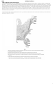
The NCBC follows the International Building Code (IBC) requirements for wind loads, with ultimate
(factored) wind speeds up to 160 mph. These panels were tested to 180 mph for wind loads across the
Southeast US. Table 1609.3.1 converts this to 139 psf for unfactored loading, which was used in the
analysis. See Attachment 1 for nominal ground wind speed reference maps from the North Carolina
Building Code.
The American Society of Civil Engineers (ASCE) Standard 7-10, Chapter 29, provides the analysis
method to convert wind speed (in mph) to pressure (psf) against the glass panel. Using Exposure
Category C (open terrain) and a height of 100 feet above ground; a 139 mph wind produces a calculated
pressure of 81psf. See Attachment 2. The three distinct support points, “spigots”, for these panels
creates stress concentrations around the supports that are best modeled using a finite element model
(FEM). A FEM model was created for this panel using Risa-3D software (version 10.0.1), that modeled
a 60” wide x 39” tall x 13mm thick tempered and laminated panel, with a 81psf surface load applied.
The model generated a 15,979 psi principal axis stress (s) in the panel. See Attachment 3.
The glass used in the panels was tested to determine its structural capacity, using a static load applied to
a test specimen. The specimen was loaded to failure, and the loading was applied to the FEM to
determine the equivalent stresses. The failure stress was 35,767 psi. This modeling shows that the
panels have calculated factor-of-safety of 2.24. See Attachment 4.
Impact Resistance
For building envelope glazing in wind-borne debris regions, glass that is part of a building envelope
must be tested for impact resistance in accordance with American Society for Testing and Materials
(ASTM) E1996. This requirement protects a closed building envelope from being penetrated and
prevents high wind pressures from filling the building, potentially blowing out windows and lifting the
roof off the building. Because these panels are not part of the building enclosure, damage from wind-