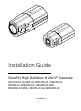
Installation Guide ClearPix High Definition H.
Important Safety Information This manual provides installation and operation information and precautions for the use of this camera. Incorrect installation could cause an unexpected fault. Before installing this equipment read this manual carefully. Please provide this manual to the owner of the equipment for future use.
• same model series. External power connections must be properly insulated. Do not connect directly to mains power for any reason. Caution — Failure to observe the following instructions may result in injury or damage to the camera. • • • • • • • • ii Do not install near any heat sources such as radiators, heat registers, stoves, or other sources of heat. Do not subject the cables to excessive stress, heavy loads or pinching. Do not open or disassemble the device. There are no user serviceable parts.
Regulatory Notices This device complies with part 15 of the FCC Rules. Operation is subject to the following two conditions: (1) This device may not cause harmful interference, and (2) this device must accept any interference received, including interference that may cause undesired operation. This Class B digital apparatus complies with Canadian ICES-003.
Other Notices Compilation and Publication Notice This manual has been compiled and published covering the latest product descriptions and specifications. The contents of this manual and the specifications of this product are subject to change without notice.
Table of Contents Overview . . . . . . . . . . . . . . . . . . . . . . . . . . . . . . 1 Front View . . . . . . . . . . . . . . . . . . . . . . . . . . . . . . . . 1 Rear View . . . . . . . . . . . . . . . . . . . . . . . . . . . . . . . . . 2 Installation . . . . . . . . . . . . . . . . . . . . . . . . . . . . . 3 Required Tools and Materials . . . . . . . . . . . . . . . . . 3 Camera Package Contents . . . . . . . . . . . . . . . . . . . 3 Installation Steps . . . . . . . . . . . . . . . . . . . . . . .
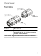
Overview Front View Camera Mount (Top and Bottom) Camera Mount (Top and Bottom) Serial Number Tag Serial Number Tag Feature Description Camera Mounts Mounting points for the camera. Mounts accept 1/4” - 20 UNC bolts commonly found on mounting brackets. Serial Number Tag Product serial number and part number label.
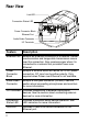
Rear View Link LED Connection Status LED Power Connector Block Ethernet Port Audio/Video Connector I/O Terminals Feature Description Ethernet Port Accepts an Ethernet connection to a network. Server communication and image data transmission occurs over this connection. Also receives power when it is connected to a network that provides Power over Ethernet. Power Connector Block Accepts a terminal block with either AC or DC power connection. DC input can be either polarity.
Installation Required Tools and Materials • • Small slotted screwdriver with 5/64” or 2 mm blade width — for connecting power when not using Power over Ethernet. Mounting bracket, enclosure or tripod. Camera Package Contents Ensure the package contains the following: • • ClearPix High Definition IP Camera Terminal block Installation Steps Complete the following procedures to install the camera. 1. 2. 3. 4. 5.
Caution — This camera is designed for indoor use only. Warning — Use only UL-listed mounting bracket suitable for the mounting surface and minimum 0.7 kg (1.5 lb) weight. Connecting Cables Refer to the diagrams in the Overview section for the location of the different connectors. To connect the cables required for proper operation, complete the following: 1. 2. 3. 4.
5. Check that the Connection Status LED indicates the correct state. For more information, see LED Indicators. Assigning an IP Address The camera automatically obtains an IP address by default. Once connected to a network, it attempts to locate and obtain an IP address from a DHCP server. If this fails, Zero Configuration Networking (Zeroconf) is used to choose an IP address. When the IP address is set using Zeroconf, the IP address is in the 169.254.0.0/16 subnet.
Aiming and Focusing the Camera Use the ClearPix Camera Installation Tool to aim and focus the camera. Consult the software user guide for more information. 1. 2. In the Image and Display settings dialog box, use the Zoom controls to achieve the desired zoom position for the camera. In the Image and Display settings dialog box, use the Auto Focus button to focus the lens. If the desired focus position was not achieved, use the focus near and far buttons to adjust the focus.
Cable Connections Connecting External Power NOTE: Do not perform this procedure if Power over Ethernet (POE) is used. If PoE is not available, the camera needs to be powered through the removable power connector block. Refer to the diagrams in this guide for the location of the power connector block. The device can be powered from 12 VDC or 24 VAC. The power consumption information is listed in the product specifications. To connect power to the power connector block, complete the following steps: 1. 2.
Connecting to External Devices External devices are connected to the camera through the I/O terminal. The pinout for the I/O terminal is shown in the following table and diagram. Table:External I/O Terminals Pin Function Description 1 Ground Ground 2 Input To activate, connect the Input to the Ground pin. To deactivate, leave disconnected or apply between 3-15 V. 3 Output When active, Output is internally connected with the Ground pin. Circuit is open when inactive.
Connecting to Microphones, Speakers and Video Monitors The camera can be connected to an external microphone, speaker and video monitor through the audio/video connector. The connector is a mini-jack (3.5 mm), and the pinout for it is shown in the following diagram. NOTE: The camera only supports line level mono audio input and an NTSC or PAL video output. The video output signal is determined by the camera flicker control setting.
LED Indicators Once the camera is connected to the network, the Connection Status LED will display the camera’s progress in connecting to the Network Video Management software. The following table describes what the LEDs indicate: Table:LED Indicators Connection State Connection Status LED Description Obtaining IP One short Address flash every second Attempting to obtain an IP address.
Reset to Factory Default Settings If the camera no longer functions as expected, you can choose to restore the camera to its factory default settings. Use the firmware revert button to reset the camera. Firmware Revert Button Figure: The firmware revert microswitch on the rear of the camera. 1. Disconnect power from the camera. 2. Using a straightened paperclip or similar tool, gently press and hold the firmware revert microswitch. While continuing to hold the microswitch, power the device.
Setting the IP Address Through the ARP/Ping Method Complete the following steps to configure the camera to use a specific IP address: 1. 2. Locate and copy down the MAC Address (MAC) listed on the Serial Number Tag for reference. Open a Command Prompt window and enter the following commands: a. arp -s For example: arp -s 192.168.1.10 00-1885-12-45-78 b. 3. 4. 12 ping -l 123 -t For example: ping -l 123 -t 192.168.1.
Specifications FBxxDN-H2 CFBxxDN-H2 MFBxxDN-H2 Camera Audio Input Line input, A/V mini-jack (3.5 mm) Video Output NTSC/PAL, A/V mini-jack (3.5 mm) Lens 4.7-84.6mm, F1.6, auto iris 3-9mm, F1.2, P-Iris 9-22mm, F1.6, P-Iris Network Network 100Base-TX Cabling Type CAT5 Connector RJ-45 API ONVIF compliant (www.onvif.
Limited Warranty & Technical Support ClearPix warrants to the original consumer purchaser, that this product will be free of defects in material and workmanship for a period of 3 years from date of purchase. The manufacturer’s liability hereunder is limited to replacement of the product, repair of the product or replacement of the product with repaired product at the discretion of the manufacturer.