
Manual
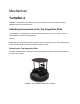

Making Modifications to the Top Integration Plate
Modifying the plate can be done roughly by hand, however a 3D model and 2D drawing of the
part is available at Github. When cutting or drilling into the plate, ensure proper safety
precautions are taken; wear safety glasses, be familiar with your tools, fasten the plate securely
to a work surface. When working with acrylic, it is best to start with a smaller hole (Ø3mm) and
enlarge it to the desired size incrementally.
To reattach the plate, apply a low to medium strength thread locker (e.g. Loctite 222). Insert the
screws and torque them to 25N-cm.
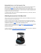
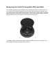
Attaching Accessories to the Base Unit
There is space for sensors to be attached to the base unit above the PCBA as well as near the
Create® 3 User Buttons and inside the Shell.
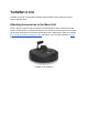
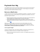
To attach accessories above the PCBA, mounting brackets can be designed for the desired
accessory and attached to the TurtleBot 4 by securing them to the standoffs. 3D models of the
TurtleBot4 are available on Github that can help in the design process.
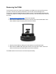
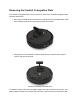
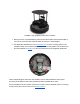
To attach accessories inside the Shell, the PCBA and the Create® 3 Integration Plate should be
removed. Inside, the existing holes can be used or additional mounting features can be
machined or 3D printed.
To attach accessories to the Create® 3, the existing holes in the plate can be used, or additional
holes can be drilled by removing the Create® 3 Integration Plate.
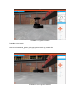
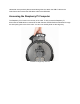
TurtleBot 4 Attachment Locations