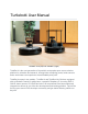
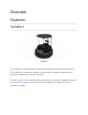
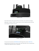
Turtlebot4 User Manual TurtleBot 4 Lite (left) and TurtleBot 4 (right) TurtleBot 4 is the next-generation of the world's most popular open source robotics platform for education and research, offering better computing power, better sensors and a world class user experience at an affordable price point. TurtleBot 4 comes in two models - TurtleBot 4 and TurtleBot Lite. Both are equipped with an iRobot® Create® 3 mobile base, a powerful Raspberry Pi 4 running ROS 2, OAK-D stereo camera, 2D LiDAR and more.
Features TurtleBot 4 TurtleBot 4 Lite Hardware Specifications Sensors RPLIDAR A1M8 OAK-D-Lite OAK-D-Pro 9 9 11 12 14 14 14 15 Resources Software Ubuntu Raspberry Pi ROS2 TurtleBot 4 iRobot® Create® 3 Luxonis SLAMTEC 16 16 16 16 16 16 17 17 17 Quick Start Powering on the robot Installing ROS2 Galactic on your PC Network Configuration WiFi Setup Find the Raspberry Pi IP on your network Create® 3 WiFi Setup TurtleBot 4 Controller Setup Updating the TurtleBot 4 Create® 3 Update over WiFi Find the IP address
User PC TurtleBot 4 Packages TurtleBot 4 Installation Debian installation Source installation Description Messages Actions Messages Services Navigation TurtleBot 4 Navigator Node Functions Configuration Buttons Example LEDs Examples Display Menu Control TurtleBot 4 Robot Installation Source installation Base GPIO Interface I2C Interface SSD1306 Configuration Robot Upstart Bringup Diagnostics Diagnostics Updater Tests ROS Tests TurtleBot 4 Desktop Installation Debian installation Source installation 30 31 3
Visualisation TurtleBot 4 Simulator Installation Dev Tools Ignition Edifice Debian installation Source installation Ignition Bringup Ignition GUI Plugins Ignition Toolbox 52 52 52 52 52 53 53 53 54 55 Sensors RPLIDAR A1M8 Connecting Installing Running OAK-D Connecting Installing Running Create® 3 Cliff Bumper Wheeldrop IR Proximity Slip and Stall Kidnap 55 56 56 56 56 56 57 57 57 57 57 58 58 58 58 58 Rviz2 View Model View Robot Rviz2 Displays LaserScan Camera TF 58 59 59 60 61 62 63 SLAM Synchronous S
Launch files Parameters Configuration Examples Navigating with Rviz2 67 67 67 67 69 Simulation Installing Ignition Gazebo Launching Ignition Gazebo 69 70 70 TurtleBot 4 Attaching Accessories to the Top Integration Plate Removing the Top Integration Plate Making Modifications to the Top Integration Plate Attaching Accessories to the Base Unit Removing the PCBA Removing the Create® 3 Integration Plate and Shell 72 72 72 73 73 74 75 TurtleBot 4 Lite Attaching Accessories to the Base Unit Removing the Cre
User USB-C Ports 92 Power Budget 92 Driving your TurtleBot 4 Keyboard Teleoperation Joystick Teleoperation Command Velocity Create® 3 Actions 95 95 96 97 97 Creating your first node (C++) Create a workspace Create a package and node Write your node Add your dependencies Create a class Subscribe to the Create® 3 interface buttons Test Create® 3 Button 1 Create a lightring publisher Publish the lightring command with a button press Toggle the lightring Your first C++ Node 98 98 98 98 99 100 101 102 103
SLAM vs Localization SLAM Localization Nav2 Launching navigation Interacting with Nav2 2D Pose Estimate Publish Point Nav2 Goal TurtleBot 4 Navigator Navigate to Pose Code breakdown Initialise the node Dock the robot Set the initial pose Wait for Nav2 Set the goal pose Undock the robot and go to the goal pose Watch navigation progress in Rviz Navigate Through Poses Code breakdown Set goal poses Navigate through the poses Watch navigation progress in Rviz Follow Waypoints Code breakdown Watch navigation prog
Restart the robot Access the RPi over Ethernet 1. Waiting to connect to bluetoothd… 2. No default controller available Common issues with the user PC 1. ros2: command not found 2.
Overview Features TurtleBot 4 TurtleBot 4 The TurtleBot 4 is a ROS2-based mobile robot intended for education and research. The TurtleBot 4 is capable of mapping its surroundings, navigation autonomously, running AI models on its camera, and more. It uses a Create® 3 as the base platform, and builds on it with the TurtleBot 4 shell and User Interface (UI) board. Inside the shell sits a Raspberry Pi 4B which runs the TurtleBot 4 software.
Raspberry Pi 4B The UI Board offers status and user LEDs, user buttons, and a 128x64 user display. Additionally, it exposes 4 USB 3.0 (type C) ports, as well as additional power ports and some Raspberry Pi pins for the user. TurtleBot 4 UI Board On top of the UI board sits a RPLIDAR A1M8 360 degree lidar, and an OAK-D-Pro camera. Above the sensors is the sensor tower, which allows the user to customize their TurtleBot4 with additional sensors or payloads.
TurtleBot 4 Lite TurtleBot 4 Lite The TurtleBot 4 Lite is a barebones version of the TurtleBot 4. It has just the necessary components for navigation, mapping, and AI applications. The TurtleBot 4 has the same Raspberry Pi 4B, which sits in the cargo bay of the Create® 3, as well as the same RPLIDAR A1M8. The camera on the TurtleBot 4 Lite is the OAK-D-Lite. Additional sensors and payloads can be attached to the Create® 3 faceplate, or placed inside the cargo bay.
Hardware Specifications Feature TurtleBot 4 Lite TurtleBot 4 Size (L x W x H) 342 x 339 x 192 mm 342 x 339 x 351 mm Weight 3270 g 3945 g Base platform iRobot® Create® 3 iRobot® Create® 3 Wheels (Diameter) 72 mm 72 mm Ground Clearance 4.5 mm 4.5 mm On-board Computer Raspberry Pi 4B 4GB Raspberry Pi 4B 4GB Maximum linear velocity 0.31 m/s in safe mode, 0.46 m/s without safe mode 0.31 m/s in safe mode, 0.46 m/s without safe mode Maximum angular velocity 1.90 rad/s 1.
VBAT @ 300 mA VBAT @1.9A 12V @ 300 mA User Power 5V @ Low current 5V @ 500 mA 3.3V @ Low current 3.3v @ 250 mA USB 2.0 (Type A) x2 USB 2.0 (Type A) x2 USB Expansion USB 3.0 (Type A) x1 USB 3.0 (Type A) x2 USB 3.
Sensors RPLIDAR A1M8 RPLIDAR A1M8 The RPLIDAR A1M8 is a 360 degree Laser Range Scanner with a 12m range. It is used to generate a 2D scan of the robots surroundings. Both the TurtleBot 4 and TurtleBot 4 Lite use this sensor. For more information, click here. OAK-D-Lite OAK-D-Lite The OAK-D-Lite camera from Luxonis uses a 4K IMX214 colour sensor along with a pair of OV7251 stereo sensors to produce high quality colour and depth images.
OAK-D-Pro OAK-D-Pro The OAK-D-Pro offers all of the same features the OAK-D-Lite has, but uses higher resolution OV9282 stereo sensors and adds an IR laser dot projector and an IR illumination LED. This allows the camera to create higher quality depth images, and perform better in low-light environments. For more information, visit the Luxonis documentation.
Resources Software Ubuntu ● Ubuntu 20.04 LTS Desktop (Focal Fossa): https://releases.ubuntu.com/20.04/ Raspberry Pi ● Raspberry Pi Imager: https://www.raspberrypi.com/software/ ● Raspberry Pi Pinout: https://pinout.xyz/ ROS2 ● Documentation: https://docs.ros.org/en/galactic/index.html ● Debian Install: https://docs.ros.org/en/galactic/Installation/Ubuntu-Install-Debians.html ● Nav2 ○ Documentation: https://navigation.ros.org/ ○ Github: https://github.
iRobot® Create® 3 ● ● ● ● ● Product details: https://edu.irobot.com/what-we-offer/create3 Hardware overview: https://iroboteducation.github.io/create3_docs/hw/overview/ Electrical overview: https://iroboteducation.github.io/create3_docs/hw/electrical/ Create® 3 Simulator: https://github.com/iRobotEducation/create3_sim irobot_create_msgs: https://github.com/iRobotEducation/irobot_create_msgs Luxonis ● OAK-D-Lite product details: https://docs.luxonis.com/projects/hardware/en/latest/pages/DM9095.
Quick Start Powering on the robot To power the robot, place it on the charging dock. The Create® 3 lightring will turn on and the Raspberry Pi will be powered as well. To power off the robot, remove it from the dock and press and hold the Power button on the Create® 3. The lightring will flash 3 times, and the Create® 3 will play a sound before turning off. Installing ROS2 Galactic on your PC Follow these instructions to install ROS2 Galactic Desktop on your PC.
CycloneDDS is configured in an XML file, and that configuration should be applied to the CYCLONEDDS_URI environment variable. Add this line to your ~/.bashrc file to automatically configure CycloneDDS each time you open your terminal: export CYCLONEDDS_URI='true' For more CycloneDDS configuration options, visit the CycloneDDS documentation.
Find the Raspberry Pi IP on your network The TurtleBot 4 will display its WiFi IP address on the display. WiFi IP address on a TurtleBot 4 For the TurtleBot 4 Lite, you will need to check the /ip topic for the new address.
On your PC, run the following commands: source /opt/ros/galactic/setup.bash ros2 topic echo /ip You should see the IP address printed out in your terminal periodically. Echoing the IP address of a TurtleBot 4 If you are unable to find the IP address with the previous methods, you can try to use: nmap -sP 192.168.1.0/24 Make sure to replace 192.168.1 with your subnet.
Once you have found the IP address, you can now ssh back into the robot with it. ssh ubuntu@xxx.xxx.xxx.xxx If you wish to put the Raspberry Pi back into AP mode, you can call sudo wifi.sh -a Create® 3 WiFi Setup ● Press both Create® 3 button 1 and 2 simultaneously until light ring turns blue Putting the Create® 3 in AP mode ● The Create® 3 is now in AP mode. Connect to its WiFi network called ‘Create-XXXX' ● In a browser go to 192.168.10.
Connecting the Create® 3 to WiFi ● Wait for it to connect to WiFi and play a chime ● On your PC, run ros2 topic list to ensure that the Create® 3 is publishing its topics TurtleBot 4 Controller Setup The TurtleBot 4 comes with an included TurtleBot 4 Controller. It is paired in advance with the Raspberry Pi. If you wish to manually pair a controller, follow these instructions: ● SSH into the TurtleBot 4 sudo bluetoothctl --agent=NoInputNoOutput ● The bluetoothd CLI interface will start.
Putting the TurtleBot 4 in pair mode ● In the CLI look for a Wireless Controller device to be found. It will have a MAC address similar to A0:5A:5C:DF:4D:7F. ● Copy the MAC address. ● In the CLI enter trust MAC_ADDRESS, replacing MAC_ADDRESS with the controllers address. ● Then, enter pair MAC_ADDRESS. ● Finally, enter connect MAC_ADDRESS. ● The CLI should report that the controller has been connected and the light on the controller will turn blue. ● Enter exit to exit the CLI.
Update over WiFi The Create® 3 can be updated through its webserver. There are two options to connect to the webserver: Find the IP address of the Create® 3 on your WiFi network. This can be done by going to your routers portal and viewing connected devices. You should see the Create® 3 in your Wireless Clients if it is connected. Enter the IP address into a browser. You will be taken to the Create® 3 webserver. Go to the Update tab and click the ‘Update' button.
● Go to the Update tab and click on the link to update from firmware file. ● Upload the latest firmware and wait for the robot to be updated. Update over USB-C Download the latest firmware from http://edu.irobot.com/create3-latest-fw. Copy the firmware to the Raspberry Pi: sudo scp ~/Downloads/Create3-G.X.Y.swu ubuntu@xxx.xxx.xxx.xxx:/home/ubuntu/ SSH into the Raspberry Pi and update the Create® 3 firmware over USB-C: sudo create_update.sh Create3-G.X.Y.swu or curl -X POST --data-binary @Create3-G.X.Y.
Source packages To update a source package you will need to use a terminal to manually pull changes. For example, updating the turtlebot4_robot package on the galactic branch: cd ~/turtlebot4_ws/src/turtlebot4_robot git checkout galactic git pull origin galactic You will then need to rebuild the packages: cd ~/turtlebot4_ws source /opt/ros/galactic/setup.bash colcon build --symlink-install source install/setup.
● The SD card should have a name like /dev/mmcblk0 or /dev/sda. ● If you wish to backup your current image, do so now: sudo dd if=/dev/ of= bs=1M Note SD_NAME is the device name (mmcblk0, sda, etc.). IMAGE_PATH is the path to where you want the image saved – e.g., ~/turtlebot4_images/backup_image. ● Get the SD flash script from turtlebot4_setup and flash the SD card: wget https://raw.githubusercontent.com/turtlebot/turtlebot4_setup/galactic/scripts/sd_flash .sh bash sd_flash.
Software ● ● ● ● ● ● ● Overview TurtleBot 4 Packages Sensors Rviz2 SLAM Nav2 Simulation Overview The TurtleBot 4 runs on Ubuntu 20.04 LTS (Focal Fossa) and currently only supports ROS2 Galactic. The TurtleBot 4 software is entirely open source under the Apache 2.0 license, and is available on the TurtleBot Github. There are 2 main computers that run software used by TurtleBot 4: the onboard Raspberry Pi 4, the Create® 3 onboard processor.
Create® 3 The Create® 3 exposes ROS2 topics, actions, and services over both WiFi and the USB-C cable powering the Raspberry Pi. This gives users access to the battery state, sensor data, docking actions, and more. While the Create® 3 can be used with just the USB-C interface, in order to view the robot model on Rviz or run software such as SLAM or Nav2 from a user PC, the Create® 3 will require a WiFi connection.
TurtleBot 4 Packages The TurtleBot 4 has 4 main repositories for software: turtlebot4, turtlebot4_robot, turtlebot4_desktop, and turtlebot4_simulator. Each repository is also a metapackage and contains one or more ROS2 packages. TurtleBot 4 The turtlebot4 repository contains common packages that are used by both turtlebot4_robot and turtlebot4_simulator. Installation Source code is available here.
Build the packages: source /opt/ros/galactic/setup.bash colcon build --symlink-install Description The turtlebot4_description package contains the URDF description of the robot and the mesh files for each component. The description can be published with the robot_state_publisher. Messages The turtlebot4_msgs package contains the custom messages used on the TurtleBot 4: ● ● ● UserButton: User Button states. UserLed: User Led control. UserDisplay: User Display data.
● ● ● ● ● ● ● ● ● ● ● ● ● ● ● ● ● Button: Status for a button. Dock: Information about the robot sensing the its dock charging station. HazardDetection: An hazard or obstacle detected by the robot. HazardDetectionVector: All the hazards and obstacles detected by the robot. InterfaceButtons: Status of the 3 interface buttons on the Create® robot faceplate. IrIntensity: Reading from an IR intensity sensor. IrIntensityVector: Vector of current IR intensity readings from all sensors.
● SLAM Async: Launches slam_toolbox with online asynchronous mapping. Recommended for use on the Raspberry Pi 4. Nav Bringup launch configuration options: ● ● ● ● ● ● ● ● ● ● namespace: Top-level namespace. ○ default: None use_namespace: Whether to apply a namespace to the navigation stack. ○ options: true, false ○ default: false slam: Whether to launch SLAM. ○ options: off, sync, async ○ default: off localization: Whether to launch localization.
ros2 launch turtlebot4_navigation nav_bringup.launch.py localization:=true slam:=off map:=/path/to/map.yaml TurtleBot 4 Navigator The TurtleBot 4 Navigator is a Python node that adds TurtleBot 4 specific functionality to the Nav2 Simple Commander. It provides a set of Python methods for navigating the TurtleBot 4. This includes docking, navigating to a pose, following waypoints, and more. Visit the Navigation Tutorials for examples.
● ○ description: Enable or disable motor stop. /robot_power: irobot_create_msgs/srv/RobotPower ○ description: Power off the robot. Action Clients: ● ● ● /dock: irobot_create_msgs/action/DockServo ○ description: Command the robot to dock into its charging station. /wall_follow: irobot_create_msgs/action/WallFollow ○ description: Command the robot to wall follow on left or right side using bump and IR sensors.
● ● ● ● wifi.interface: The Wi-Fi interface being used by the computer. This is used to find the current IP address of the computer. menu.entries: Set menu entries to be displayed. Each entry must be one of the support functions. buttons: Set the function of Create® 3 and HMI buttons. controller: Set the function of TurtleBot 4 Controller buttons. Buttons The Buttons class in turtlebot4_node provides functionality to all buttons on the robot.
Example Lets say we want the TurtleBot 4 to have the following button functions: ● ● ● Make a short press of Create® 3 button 1 toggle EStop. Power off robot with 5 second press of Home on the TurtleBot 4 Controller. Short press of HMI button 1 performs Wall Follow Left, long press of 3 seconds performs Wall Follow Right. Create a new yaml file: cd /home/ubuntu/turtlebot4_ws touch example.yaml Use your favourite text editor and paste the following into example.
Status LEDs: ● ● ● ● ● POWER: Always ON while turtlebot4_node is running. MOTOR: ON when wheels are enabled, OFF when wheels are disabled. ○ Wheel status is reported on the /wheel_status topic. COMMS: ON when communication with Create® 3 is active. OFF otherwise. ○ Receiving data on the /battery_state topic implies that communication is active. WIFI: ON when an IP address can be found for the Wi-Fi interface specified in the configuration. BATTERY: Colour and pattern will vary based on battery percentage.
User 1: Solid Green Set USER_1 OFF: ros2 topic pub /hmi/led turtlebot4_msgs/msg/UserLed "led: 0 color: 0 blink_period: 1000 duty_cycle: 1.
User 1: Off Blink USER_2 red at 1hz with 50% duty cycle: ros2 topic pub /hmi/led turtlebot4_msgs/msg/UserLed "led: 1 color: 2 blink_period: 1000 duty_cycle: 0.
User 2: Red, 1hz, 50% Display The Display class in turtlebot4_node controls the HMI display of the TurtleBot 4. The physical display is a 128x64 OLED which is controlled over I2C with a SSD1306 driver. The display has a header line which contains the IP address of the Wi-Fi interface specified in configuration, as well as the battery percentage received on the /battery_state topic. The display also has 5 additional lines which are used for the menu by default.
● ● The select function will call the currently selected menu entry. This can trigger an action such as docking, a service such as EStop, or display a message such as the Help message. This function is mapped to user button 1 by default. The back function allows the user to return back to the menu from a message screen. If the menu is already showing the menu entries, it will return to showing the first 5 menu entries and the first entry will be highlighted.
cd ~/turtlebot4_ws/src git clone https://github.com/turtlebot/turtlebot4_robot.git Install dependencies: cd ~/turtlebot4_ws vcs import src < src/turtlebot4_robot/dependencies.repos rosdep install --from-path src -yi Build the packages: source /opt/ros/galactic/setup.bash colcon build --symlink-install Base The turtlebot4_base package contains the source code for the rclcpp node turtlebot4_base_node which runs on the physical robot.
I2C Interface The linux I2C drivers are used to read and write data on the I2C buses of the Raspberry Pi. The display's SSD1306 driver is connected to the i2c-3 device by default, but other buses are available too. SSD1306 The SSD1306 is a driver for OLED displays. It receives commands over a communication bus (I2C for the TurtleBot 4) and controls how the physical display behaves. The TurtleBot 4 uses a modified version of this STM32 SSD1306 driver to write pixels, shapes and characters to the display.
Note The value for each GPIO device is the GPIO number, NOT the pin number. Robot Upstart The robot uses the robot_upstart package to install the bringup launch files as a background process that launches when the robot starts. The launch files are located under the turtlebot4_bringup package. To check if the TurtleBot 4 service is running, use this command on the Raspberry Pi: systemctl | grep turtlebot4 If the service is active, the CLI will echo turtlebot4.
ros2 run robot_upstart install turtlebot4_bringup/launch/lite.launch.py --job turtlebot4 --rmw rmw_cyclonedds_cpp --rmw_config /etc/cyclonedds_rpi.xml To uninstall, use this command: ros2 run robot_upstart uninstall turtlebot4 Once uninstalled, the launch file will no longer be launched on boot. Bringup The turtlebot4_bringup package contains the launch and configuration files to run the robots software. Launch files: ● ● ● ● ● ● Joy Teleop: Launches nodes to enable the bluetooth controller.
Diagnostic topics: ● ● ● ● ● ● ● ● ● ● ● /battery_state: Check battery voltage and percentage. /wheel_status: Check if wheels are enabled. /dock: Check if the robot is docked. /scan: Check the frequency of laser scans from the RPLIDAR. /left/image: Check the frequency of images from the left OAK-D camera. /right/image: Check the frequency of images from the right OAK-D camera. /color/image: Check the frequency of images from the OAK-D colour sensor.
ROS Tests The ROS tests use ROS topics and actions to test various system functionality. Test results are saved to ~/turtlebot4_test_results/Y_m_d-H_M_S where Y_m_d-H_M_S is the date and time of the test. A rosbag is also recorded for the duration of the test and saved to the same location.
Running the Light Ring test
TurtleBot 4 Desktop The turtlebot4_desktop metapackage contains packages used for visualising and interfacing with the TurtleBot 4 from a PC. Installation Source code is available here. Note The turtlebot4_desktop metapackage can be installed on a PC running Ubuntu Desktop 20.04 with ROS2 Galactic.
Visualisation The turtlebot4_viz package contains launch files and configurations for viewing the robot in Rviz2, and viewing the diagnostics. Launch files: ● ● ● View Diagnostics: Launches rqt_robot_monitor to view diagnostic data. View Model: Launches rviz2. Used to view the model and sensor data. View Robot: Launches rviz2. Used to view the robot while navigating. TurtleBot 4 Simulator The turtlebot4_simulator metapackage contains packages used to simulate the TurtleBot 4 in Ignition Gazebo.
Debian installation To install the metapackage through apt: sudo apt update sudo apt install ros-galactic-turtlebot4-simulator ros-galactic-irobot-create-nodes Source installation To manually install this metapackage from source, clone the git repository: cd ~/turtlebot4_ws/src git clone https://github.com/turtlebot/turtlebot4_simulator.git Install dependencies: cd ~/turtlebot4_ws vcs import src < src/turtlebot4_simulator/dependencies.
Ignition launch configuration options: ● ● ● ● ● ● ● model: Which TurtleBot 4 model to use. ○ options: standard, lite ○ default: standard rviz: Whether to launch rviz. ○ options: true, false ○ default: false slam: Whether to launch SLAM. ○ options: off, sync, async ○ default: off nav2: Whether to launch Nav2. ○ options: true, false ○ default: false param_file: Path to parameter file for turtlebot4_node. ○ default: /path/to/turtlebot4_ignition_bringup/config/turtlebot4_node.
TurtleBot 4 HMI GUI plugin Ignition Toolbox The turtlebot4_ignition_toolbox package contains the source code for the TurtleBot 4 HMI node. The TurtleBot 4 HMI node acts as a bridge between the turtlebot4_node and ros_ign_bridge to convert the custom TurtleBot 4 messages into standard messages such as Int32 and String.
Sensors RPLIDAR A1M8 Connecting The RPLIDAR connects to the TurtleBot 4 with a micro USB to USB-A cable. The sensor does not require high data throughput, so using a USB 2.0 port is sufficient. Once connected, the RPLIDAR should register on the Raspberry PI as a USB device. If the udev rules are installed, the RPLIDAR will appear as /dev/RPLIDAR. Otherwise it will be /dev/ttyUSB0. To check that the USB device exists, use the command ls /dev/RPLIDAR If the device exists, the terminal will echo /dev/RPLIDAR.
OAK-D Connecting The OAK-D cameras are connected to the Raspberry Pi with a USB-C to USB-A cable. The cameras requires high data throughput so using a USB 3.0 port is highly recommended. Installing The OAK-D drivers are installed by default on all TurtleBot 4's. To manually install, follow the instructions on the DepthAI ROS github. Running The default node used by the TurtleBot 4 can be launched: ros2 launch turtlebot4_bringup oakd.launch.py Other nodes are available in the DepthAI ROS examples package.
The Create® 3 has 4 cliff sensors located on the front half of the robot. These sensors measure the distance from the robot to the ground, and prevent the robot from falling off of cliffs. Bumper The bumper is used by the Create® 3 to detect objects or walls that the robot has run in to. It can trigger reflexes to recoil from the object, or use the information to follow the wall. Wheeldrop The wheeldrop is the spring on which the Create® 3 wheels sit.
Rviz2 Rviz2 is a port of Rviz to ROS2. It provides a graphical interface for users to view their robot, sensor data, maps, and more. It is installed by default with ROS2 and requires a desktop version of Ubuntu to use. turtlebot4_desktop provides launch files and configurations for viewing the TurtleBot 4 in Rviz2. View Model To inspect the model and sensor data, run ros2 launch turtlebot4_viz view_model.launch.py.
View Robot For a top down view of the robot in its environment, run ros2 launch turtlebot4_viz view_robot.launch.py. This is useful when mapping or navigating with the robot Rviz2 launched with the View Robot configuration Rviz2 Displays Rviz2 offers support for displaying data from various sources. Displays can be added using the "Add" button.
Adding Displays in Rviz2
LaserScan The LaserScan display shows data for sensor_msgs/msg/LaserScan messages. On the TurtleBot 4 the RPLIDAR supplies this data on the /scan topic. LaserScan displayed in Rviz2 Camera The Camera display shows camera images from sensor_msgs/msg/Image messages. The OAK-D cameras publish images on the /color/preview/image and /stereo/depth topics.
Camera image displayed in Rviz2
TF The TF display can be used to visualise the links that make up the robot. When you first add the TF display, it will show every link that makes up the robot. TF with default settings You can uncheck the "All Enabled" box, and then select the links you wish to see.
SLAM Simultaneous localization and mapping (SLAM) is a method used in robotics for creating a map of the robots surroundings while keeping track of the robots position in that map. The TurtleBot 4 uses slam_toolbox to generate maps by combining odometry data from the Create® 3 with laser scans from the RPLIDAR. slam_toolbox supports both synchronous and asynchronous SLAM nodes. Map generated by slam_toolbox Synchronous SLAM Synchronous SLAM requires that the map is updated everytime new data comes in.
proccessing power. This approach is ideal for use on the TurtleBot 4's Raspberry Pi. The default parameters for asynchronous SLAM use a reduced map resolution to further improve performance on the Pi. Launching asynchronous SLAM: ros2 launch turtlebot4_navigation slam_async.launch.
Nav2 Nav2 is the official navigation stack in ROS2. Nav2 can be used to calculate and execute a travel path for the robot by using a map of its surroundings. The map can be loaded at launch or generated with SLAM while navigating. Launching Navigation Launch files ● Nav Bringup: Launches Nav2 nodes, with the option to launch SLAM or Localization as well. Parameters ● ● ● ● ● nav2: Whether to launch Nav2 nodes. ○ options: [true, false] ○ default: true slam: Launch SLAM along with Nav2.
Examples Launching Nav2 with synchronous SLAM: ros2 launch turtlebot4_navigation nav_bringup.launch.py slam:=sync The map and costmaps can be viewed in Rviz2: ros2 launch turtlebot4_viz view_robot.launch.py Nav2 with SLAM Obstacles that are detected on the map will have a padding around with a radius equivalent to the radius of the robot. When navigating, Nav2 will drive the robot outside of the padded area to avoid hitting obstacles.
Navigating with Rviz2 The easiest way to set a navigation goal is to use Nav2 Goal in Rviz2. With Nav2 running, select the Nav2 Goal tool at the top of Rviz2, and click the location on the map where you would like to navigate to.
Simulation The simulator allows the user to test the robot without the need for a physical robot. It has all of the same functionality as the real robot. The TurtleBot 4 can be simulated using Ignition Gazebo. Unlike Gazebo, Ignition Gazebo does not natively support ROS. Instead, it has its own transport stack with a similar topic and node implementation. To communicate with ROS, we can use the ros_ign_bridge. This ROS node translates data from ROS to Ignition, and vice versa.
TurtleBot 4 in Ignition Gazebo TurtleBot 4 Lite launch: ros2 launch turtlebot4_ignition_bringup ignition.launch.
Mechanical TurtleBot 4 TurtleBot 4 is designed to be modified to meet your needs and make it possible to attach additional sensors and accessories. Attaching Accessories to the Top Integration Plate The TurtleBot 4 is equipped with an acrylic plate at the top that is easy to modify in order to attach additional sensors and peripherals. Warning Modifications to the plate should only be done when it is removed from the robot, attempting to modify the plate while mounted can cause the plastic to crack.
Making Modifications to the Top Integration Plate Modifying the plate can be done roughly by hand, however a 3D model and 2D drawing of the part is available at Github. When cutting or drilling into the plate, ensure proper safety precautions are taken; wear safety glasses, be familiar with your tools, fasten the plate securely to a work surface. When working with acrylic, it is best to start with a smaller hole (Ø3mm) and enlarge it to the desired size incrementally.
Removing the PCBA To access the inside of the "Shell" of the TurtleBot4, the PCBA can be removed. Ensure that you have a safe spot to place the PCBA when it is removed to prevent damage to the components. It is recommended that this procedure is done on an Electrostatic Discharge Mat to protect the PCBA from damage caused by static electricity. Follow the steps below to remove the PCBA. 1. Remove the Top Integration Plate and the four standoffs. 2.
Removing the Create® 3 Integration Plate and Shell The Create® 3 Integration Plate and Shell can be removed with the rest of the assembly on or off. To remove the Create® 3 Integration Plate, first open and remove the rear Create® 3 tray. Then disconnect the USB C cable and the power harness from the Create® 3 base. Feed these cables through the slot at the back of the Create® 3. Using the tabs on the Create® 3, twist the plate counter-clockwise until it snaps to unlock it and remove the plate.
TurtleBot 4 Lite TurtleBot Lite is built on the iRobot Create® 3 learning platform which features an easy to modify integration plate. Attaching Accessories to the Base Unit There is space for sensors and accessories to be attached to the base unit around the Oak Camera and RPILIDAR. To attach accessories to the Create® 3, the existing holes in the plate can be used. These Ø3.5mm holes are spaced apart 10mm. Alternatively, holes can be drilled by removing the Create® 3 Integration Plate.
Removing the Create® 3 Integration Plate The Create® 3 Integration Plate can be removed. To remove the Create® 3 Integration Plate follow the steps below. 1. Disconnect the USB cables connected to the Oak-D Camera and the RPLIDAR. Feed these cables through the slot opening at the back of the Robot. TurtleBot 4 Lite Cable Passthrough 1. Using the tabs on the Create® 3, twist the plate counter-clockwise until it snaps to unlock it and remove the plate.
cables that were previously disconnected through the slot. Attach the USB-C cable to the Oak-Camera and connect the USB Micro cable to the RPLIDAR. Accessing the Raspberry Pi Computer The Raspberry Pi is found in the rear tray of the robot. To fully access the Raspberry Pi, disconnect the USB cables connected to the Oak Camera and RPLIDAR and feed them through the slot opening at the rear of the robot. You can now carefully slide out the cargo bay.
Payloads Over 9kg The TurtleBot4 is able to perform with heavier payloads over 9 kg, however some mechanical and software changes must be made for ideal operation. If these changes are not used the system may become unstable and difficult to control. Mechanical Modification In order to ensure the robot is as stable as possible during operation, it is important to mount the payload such that its center of gravity (COG) is fully supported by the wheelbase. This can be achieved through two methods: 1.
TurtleBot 4 Top Integration Plate screw locations 1. Remove the four round standoffs by hand and set them aside. Note that the PCBA is now free to move and care should be taken to ensure it is not damaged. 2. Use alternative standoffs (e.g. from Mcmaster Carr) or other mounting options. The threaded inserts of the robot are M4x0.7mm. The mounting pattern can be taken from 3D CAD available on Github or it can be transferred from the integration plate itself.
Note The minimum clearance to accommodate the OAK-D-Pro is 108mm. For the OAK-D-Lite it is 102mm. Example The pictures below show a Clearpath Robotics Hackday project where a NED2 Robot manipulator (8.9kg) mounted on top of a TurtleBot4 Lite using 4X2 M4 standoffs (Mcmaster Carr P/N 98952A450) and an integration plate from a TurtleBot4 Standard.The manipulator was mounted such that the COG was further forward and supported by the front caster wheel. An external NEC ALM 12V7 Battery (0.
TurtleBot 4 Lite with a NED2 arm
Software Modifications Velocity and acceleration limits should be set appropriately to maintain stability when driving the robot. Otherwise you may find that the robot will shake, stall, or not drive as commanded. Acceleration Limits The acceleration limit on the Create® 3 can be changed using the wheel_accel_limit parameter of the motion_control node. ros2 param set /motion_control wheel_accel_limit 300 The acceleration value can be between 1 and 900.
Command Velocity If you are manually sending the velocity through the /cmd_vel topic, simply reduce the velocity values to an appropriate level. Create® 3 Actions If you are driving the robot through one of the Create® 3 actions, you can set velocity limits in the action goal. Nav2 To limit velocity during navigation, you can create a modified nav2.yaml configuration file. Changing parameters such as controller_server.FollowPath.max_vel_x will limit the velocity commands sent by the Nav2 stack.
Electrical Create® 3 On the TurtleBot 4, the connection of the User Interface board with the Create® 3 robot is only through the VBAT connector J7, which uses JST XH-style connector. The connector has been marked with Positive and Negative signs on the board (Positive being pin 1). The VBAT line is fused with a PTC fuse rated at 2A. Create® 3 Power Adapter (left) and J7 connector (right) The Create® 3 power adapter also supplies the Raspberry Pi 4 with power and communication through a USB 2.
Raspberry Pi 4B The Raspberry Pi 4 is present on both the TurtleBot 4 and TurtleBot 4 Lite. On the TurtleBot 4 it can be found inside the shell, while on the Lite it is mounted in the Create® 3 cargo bay. The TurtleBot 4 connects the Raspberry Pi with the User Interface Board through a 40 pin connector and a USB 3.0 (Type B) cable. The USB 3.0 type cable enables communication to 4 USB-C ports on the UI board, while the ribbon cable passes the 40 GPIO pins of the Raspberry Pi through to the UI Board.
User Interface PCBA Note The User Interface PCBA is only available on the TurtleBot 4 and NOT the TurtleBot 4 Lite. Overview The TurtleBot 4 comes with an additional User Interface board that expands on the Raspberry Pi 4 functionality to give the user ease of control over the Create 3 robot and Raspberry Pi and to act as an expansion board for addons, sensors, gadgets the user might have in mind to utilize.
User I/O The TurtleBot 4 has a 2x20 pin internal connector connecting it to the Raspberry Pi via a flex cable, and another 2x12 pin connector allowing the user to access the remaining GPIOs and a set of 5V, and 3.3V power pins coming from the Raspberry Pi. The IO interface between the 2x20 connector and 2x12 connector and the available GPIOs to the user are shown in Table 1, and 2. The GPIO numbers are a direct match to the Raspberry Pi 4 GPIO.
GPIO6 USER2_GRN_LED 31 32 USER_PORT GPIO13 DISPLAY-RST 33 34 GND GPIO19 USER_SW1 35 36 USER_SW2 GPIO16 GPIO26 USER_SW3 37 38 USER_SW4 GPIO20 GND 39 40 USER2_RED_LED GPIO21 Note ALL USER_PORTs are routed to the 2X12 Auxiliary connectors Table 2: 2x12 User I/O Pinout GPIO # Function Pin # Pin # Function GPIO # 3V3_RPi 1 2 5V_RPi GPIO2 USER_PORT 3 4 5V_RPi GPIO3 USER_PORT 5 6 GND GND 7 8 USER_PORT GPIO14 3V3_RPi 9 10 USER_PORT GPIO15 GPIO0 EEPROM_SD 1
User Power In addition to these GPIO ports, the user has two additional power ports available supplying 3.3V, 5V, 12V, VBAT (14.4V), and two grounds each. TurtleBot 4 Additional Power Ports The pinout and power ratings can be found in Table 3.
Table 3: User Power Port Pinout Pinout Sourc e Max current output (mA) Fuse Hold at (mA) VBAT 300 350 2 12V 300 350 3 GND 4 5V 500 500 5 3V3 250 300 6 GND 1 Molex Picoblade 6-Pin cable assembly The two connectors are both 6-Pin Molex PicoBlade P/N 0532610671. The cable assembly needed to use these connectors are P/N 0151340602.
User USB-C Ports The are 4 USB-C ports that go through an integrated hub on the User Interface board and connect to the Raspberry Pi through a single USB 3.0 cable. The current available to all 4 ports is 3A. Additionally, each individual port is current limited to 3A. In other words, each port is capable of supplying 3A if the others aren't in use, or the available 3A is shared amongst ports that are in use.
Power Budget The total power made available by the Create 3 output power adapter is 28.8W. This supplies the USB-C connector mated to Raspberry Pi, and the two pin auxiliary VBAT connector combined. Since the two connectors share this power amongst them, a rise in consumption of one will lead to reduction of available power for the other.
Table 2: Maximum power consumption of individual components and systems Source Operating Voltage (V) Max current draw (A) Max Power (W) ~40 User Interface Board 4 USB-C ports 5 3 15 USB Hub Controller 1.2, 3.3 1.3 1.8 OLED Display 12 0.031 0.372 User LEDs 5 0.007 0.17 USER PWR Ports VBAT 0.3 4.32 12 0.3 3.6 5 0.5 2.5 3.3 0.25 0.825 OAK-D-Lite 5 1 5 OAK-D-Pro (connected to RPi) 5 1 5 OAK-D-Pro (connected to UI Board) 5 1.5 7.5 RPLIDAR A1M8 5 0.
Tutorials Driving your TurtleBot 4 There are several methods to get your TurtleBot 4 moving. Note The robot must first be set up and connected to Wi-Fi before it can be driven. Check out the Quick Start section if you have not already. Keyboard Teleoperation The simplest way to get your robot driving is to use a keyboard application on your PC.
teleop_twist_keyboard CLI Press i to drive forward, j to rotate left, and so on. You can also adjust linear and angular speeds on the go. Joystick Teleoperation If you have a TurtleBot 4 controller or have your own Bluetooth controller, you can drive the robot with it. First, make sure that your controller is paired and connects to the robot. If you have a TurtleBot 4 controller, press the home button and check that the controller's light turns blue.
Note The default configuration for the joy_teleop nodes will only work for the TurtleBot 4 controller and PS4 controllers. You may need to create your own config file if the button mappings on your controller differ. To drive the robot, press and hold either L1 or R1, and move the left joystick. By default, L1 will drive the robot at ‘normal' speeds, and R1 will drive the robot at ‘turbo' speeds. The buttons can be changed in the configuration file.
Creating your first node (C++) This tutorial will go through the steps of creating a ROS2 package and writing a ROS2 node in C++. For a Python example, click here. These steps are similar to the ROS2 Tutorial, but focus on interacting with the TurtleBot 4. For source code, click here. Note You can follow this tutorial on either the Raspberry Pi of your TurtleBot 4, or your PC.
Add your dependencies For this tutorial, we will need to use the rclcpp and irobot_create_msgs packages. The rclcpp package allows us to create ROS2 nodes and gives us full access to all the base ROS2 functionality in C++. The irobot_create_msgs package gives us access to the custom messages used by the Create® 3 for reading the button presses and controlling the lightring. In your CMakeLists.
Create a class Now that the dependencies are set, we can create a class that inherits from the rclcpp::Node class. We will call this class TurtleBot4FirstNode. class TurtleBot4FirstNode : public rclcpp::Node { public: TurtleBot4FirstNode() : Node("turtlebot4_first_cpp_node") {} }; Notice that our class calls the Node constructor and passes it the name of our node, turtlebot4_first_cpp_node. We can now create our node in the main function and spin it.
Subscribe to the Create® 3 interface buttons Our next step is to subscribe to the Create® 3 interface buttons topic to receive button presses. We will need to create a rclcpp::Subscription as well as a callback function for the subscription. The callback function will be called every time we receive a message on the interface buttons topic.
ROS2 topic information Test Create® 3 Button 1 Now that we are subscribed, lets test out our node by printing a message every time button 1 is pressed. Edit the interface_buttons_callback function to look like this: // Interface buttons subscription callback void interface_buttons_callback( const irobot_create_msgs::msg::InterfaceButtons::SharedPtr create3_buttons_msg) { // Button 1 is pressed if (create3_buttons_msg->button_1.
Now every time we receive a message on the /interface_buttons topic we will check if button 1 is pressed, and if it is then the node will print a message. To test this out, we will need to build our package using colcon: cd ~/turtlebot4_ws colcon build --packages-select turtlebot4_cpp_tutorials source install/local_setup.bash The --packages-select flag allows you to enter any number of packages that you want to build, in case you don't want to build all packages in your workspace.
class TurtleBot4FirstNode : public rclcpp::Node { public: TurtleBot4FirstNode() : Node("turtlebot4_first_cpp_node") { // Subscribe to the /interface_buttons topic interface_buttons_subscriber_ = this->create_subscription( "/interface_buttons", rclcpp::SensorDataQoS(), std::bind(&TurtleBot4FirstNode::interface_buttons_callback, this, std::placeholders::_1)); // Create a publisher for the /cmd_lightring topic lightring_publisher_ = this->create_publisher
void button_1_function() { // Create a ROS2 message auto lightring_msg = irobot_create_msgs::msg::LightringLeds(); // Stamp the message with the current time lightring_msg.header.stamp = this->get_clock()->now(); // Override system lights lightring_msg.override_system = true; // LED 0 lightring_msg.leds[0].red = 255; lightring_msg.leds[0].blue = 0; lightring_msg.leds[0].green = 0; // LED 1 lightring_msg.leds[1].red = 0; lightring_msg.leds[1].blue = 255; lightring_msg.leds[1].
This function creates a LightringLeds message and populates the parameters. We first stamp the message with the current time: lightring_msg.header.stamp = this->get_clock()->now(); Then we set the override_system parameter to true so that our command overrides whatever commands the Create® 3 is sending to the lightring. lightring_msg.override_system = true; Next, we populate the 6 LEDs in the leds array with whatever colours we want. // LED 0 lightring_msg.leds[0].red = 255; lightring_msg.leds[0].
Tip Each RGB value can be set between 0 and 255. You can look up the RGB value of any color and set it here. Finally, we publish the message. self.lightring_publisher.publish(lightring_msg) Publish the lightring command with a button press Now we can connect our interface button subscription to our lightring publisher. Simply call button_1_function inside the interface_buttons_callback.
Toggle the lightring You will notice that once you have set the lightrings LEDs they will remain like that forever. Lets make the button toggle the light on or off each time we press it.
lightring_msg.leds[3].blue = 255; lightring_msg.leds[3].green = 0; // LED 4 lightring_msg.leds[4].red = 255; lightring_msg.leds[4].blue = 0; lightring_msg.leds[4].green = 255; // LED 5 lightring_msg.leds[5].red = 0; lightring_msg.leds[5].blue = 255; lightring_msg.leds[5].green = 255; } // Lights are currently on else { // Disable system override. The system will take back control of the lightring. lightring_msg.
TurtleBot4FirstNode() : Node("turtlebot4_first_cpp_node"), lights_on_(false) { // Subscribe to the /interface_buttons topic interface_buttons_subscriber_ = this->create_subscription( "/interface_buttons", rclcpp::SensorDataQoS(), std::bind(&TurtleBot4FirstNode::interface_buttons_callback, this, std::placeholders::_1)); // Create a publisher for the /cmd_lightring topic lightring_publisher_ = this->create_publisher( "/cmd_ligh
lightring_msg.leds[0].blue = 0; lightring_msg.leds[0].green = 0; // LED 1 lightring_msg.leds[1].red = 0; lightring_msg.leds[1].blue = 255; lightring_msg.leds[1].green = 0; // LED 2 lightring_msg.leds[2].red = 0; lightring_msg.leds[2].blue = 0; lightring_msg.leds[2].green = 255; // LED 3 lightring_msg.leds[3].red = 255; lightring_msg.leds[3].blue = 255; lightring_msg.leds[3].green = 0; // LED 4 lightring_msg.leds[4].red = 255; lightring_msg.leds[4].blue = 0; lightring_msg.leds[4].
// Lights on status bool lights_on_; }; int main(int argc, char * argv[]) { rclcpp::init(argc, argv); rclcpp::spin(std::make_shared()); rclcpp::shutdown(); return 0; } Don't forget to build the package again before running the node.
Creating your first node (Python) This tutorial will go through the steps of creating a ROS2 package and writing a ROS2 node in Python. For a C++ example, click here. These steps are similar to the ROS2 Tutorial, but focus on interacting with the TurtleBot 4. For source code, click here. Note You can follow this tutorial on either the Raspberry Pi of your TurtleBot 4, or your PC.
Add your dependencies For this tutorial, we will need to use the rclpy and irobot_create_msgs packages. The rclpy package allows us to create ROS2 nodes and gives us full access to all the base ROS2 functionality in Python. The irobot_create_msgs package gives us access to the custom messages used by the Create® 3 for reading the button presses and controlling the lightring. In package.
Subscribe to the Create® 3 interface buttons Our next step is to subscribe to the Create® 3 interface buttons topic to receive button presses. We will need to create a rclpy.Subscription as well as a callback function for the subscription. The callback function will be called every time we receive a message on the interface buttons topic. class TurtleBot4FirstNode(Node): lights_on_ = False def __init__(self): super().__init__('turtlebot4_first_python_node') # Subscribe to the /interface_buttons topic self.
ROS2 topic information Test Create® 3 Button 1 Now that we are subscribed, lets test out our node by printing a message every time button 1 is pressed. Edit the interface_buttons_callback function to look like this: # Interface buttons subscription callback def interface_buttons_callback(self, create3_buttons_msg: InterfaceButtons): # Button 1 is pressed if create3_buttons_msg.button_1.is_pressed: self.get_logger().
The --symlink-install allows us to install a symbolic link to our Python script, rather than a copy of the script. This means that any changes we make to the script will be applied to the installed script, so we don't need to rebuild the package after each change. The --packages-select flag allows you to enter any number of packages that you want to build, in case you don't want to build all packages in your workspace.
Create a lightring publisher Now that we can receive a button press, lets create a lightring publisher. class TurtleBot4FirstNode(Node): def __init__(self): super().__init__('turtlebot4_first_python_node') # Subscribe to the /interface_buttons topic self.interface_buttons_subscriber = self.create_subscription( InterfaceButtons, '/interface_buttons', self.interface_buttons_callback, qos_profile_sensor_data) # Create a publisher for the /cmd_lightring topic self.lightring_publisher = self.
# LED 1 lightring_msg.leds[1].red = 0 lightring_msg.leds[1].blue = 255 lightring_msg.leds[1].green = 0 # LED 2 lightring_msg.leds[2].red = 0 lightring_msg.leds[2].blue = 0 lightring_msg.leds[2].green = 255 # LED 3 lightring_msg.leds[3].red = 255 lightring_msg.leds[3].blue = 255 lightring_msg.leds[3].green = 0 # LED 4 lightring_msg.leds[4].red = 255 lightring_msg.leds[4].blue = 0 lightring_msg.leds[4].green = 255 # LED 5 lightring_msg.leds[5].red = 0 lightring_msg.leds[5].blue = 255 lightring_msg.leds[5].
Next, we populate the 6 LEDs in the leds array with whatever colours we want. # LED 0 lightring_msg.leds[0].red = 255 lightring_msg.leds[0].blue = 0 lightring_msg.leds[0].green = 0 # LED 1 lightring_msg.leds[1].red = 0 lightring_msg.leds[1].blue = 255 lightring_msg.leds[1].green = 0 # LED 2 lightring_msg.leds[2].red = 0 lightring_msg.leds[2].blue = 0 lightring_msg.leds[2].green = 255 # LED 3 lightring_msg.leds[3].red = 255 lightring_msg.leds[3].blue = 255 lightring_msg.leds[3].
Finally, we publish the message. self.lightring_publisher.publish(lightring_msg) Publish the lightring command with a button press Now we can connect our interface button subscription to our lightring publisher. Simply call button_1_function inside the interface_buttons_callback. # Interface buttons subscription callback def interface_buttons_callback(self, create3_buttons_msg: InterfaceButtons): # Button 1 is pressed if create3_buttons_msg.button_1.is_pressed: self.get_logger().
Add a boolean to keep track of the light state: class TurtleBot4FirstNode(Node): lights_on_ = False def __init__(self): And modify button_1_function to toggle the light: # Perform a function when Button 1 is pressed def button_1_function(self): # Create a ROS2 message lightring_msg = LightringLeds() # Stamp the message with the current time lightring_msg.header.stamp = self.get_clock().now().to_msg() # Lights are currently off if not self.lights_on_: # Override system lights lightring_msg.
lightring_msg.leds[4].blue = 0 lightring_msg.leds[4].green = 255 # LED 5 lightring_msg.leds[5].red = 0 lightring_msg.leds[5].blue = 255 lightring_msg.leds[5].green = 255 # Lights are currently on else: # Disable system override. The system will take back control of the lightring. lightring_msg.override_system = False # Publish the message self.lightring_publisher.publish(lightring_msg) # Toggle the lights on status self.lights_on_ = not self.
# Create a publisher for the /cmd_lightring topic self.lightring_publisher = self.create_publisher( LightringLeds, '/cmd_lightring', qos_profile_sensor_data) # Interface buttons subscription callback def interface_buttons_callback(self, create3_buttons_msg: InterfaceButtons): # Button 1 is pressed if create3_buttons_msg.button_1.is_pressed: self.get_logger().info('Button 1 Pressed!') self.
# LED 4 lightring_msg.leds[4].red = 255 lightring_msg.leds[4].blue = 0 lightring_msg.leds[4].green = 255 # LED 5 lightring_msg.leds[5].red = 0 lightring_msg.leds[5].blue = 255 lightring_msg.leds[5].green = 255 # Lights are currently on else: # Disable system override. The system will take back control of the lightring. lightring_msg.override_system = False # Publish the message self.lightring_publisher.publish(lightring_msg) # Toggle the lights on status self.lights_on_ = not self.
Generating a map In this tutorial we will be mapping an area by driving the TurtleBot 4 around and using SLAM. Start by making sure that the area you will be mapping is clear of unwanted obstacles. Ideally, you don't want people or animals moving around the area while creating the map. Launch SLAM First, make sure that the RPLIDAR and description nodes are running on the TurtleBot 4. Then run SLAM. It is recommended to run synchronous SLAM on a remote PC to get a higher resolution map.
Rviz2 showing a map generate by SLAM Drive the TurtleBot 4 Use any method to drive the robot around the area you wish to map. Check out the driving tutorial if you are unsure of how to drive the robot. Keep watch of RVIZ as you drive the robot around the area to make sure that the map gets filled out properly.
Save the map Once you are happy with your map, you can save it with the following command: ros2 service call /slam_toolbox/save_map slam_toolbox/srv/SaveMap "name: data: 'map_name'" This will save the map to your current directory. View the map Once the map is saved it will generate a map_name.pgm file which can be viewed in an image editor. A map_name.yaml file is also created. You can edit this file to adjust the map parameters.
Navigation This tutorial will cover various methods of navigating with the TurtleBot 4 and Nav2. SLAM vs Localization There are two localization methods we can use to figure out where the robot is on the map: SLAM or Localization. SLAM allows us to generate the map as we navigate, while localization requires that a map already exists. SLAM SLAM is useful for generating a new map, or navigating in unknown or dynamic environments.
ros2 launch turtlebot4_ignition_bringup ignition.launch.py nav:=true slam:=off localization:=true This will launch the simulation in the default depot world and will use the existing depot.yaml file for the map. If you are using a different world you will need to create a map for it and pass that in as a launch argument. For example: ros2 launch turtlebot4_ignition_bringup ignition.launch.py nav:=true slam:=off localization:=true world:=classroom map:=classroom.
2D Pose Estimate The 2D Pose Estimate tool is used in localization to set the approximate initial pose of the robot on the map. This is required for the Nav2 stack to know where to start localizing from. Click on the tool, and then click and drag the arrow on the map to approximate the position and orientation of the robot. Setting the initial pose Publish Point The Publish Point tool allows you to click on a point on the map, and have the coordinates of that point published to the /clicked_point topic.
Getting a point coordinate Nav2 Goal The Nav2 Goal tool allows you to set a goal pose for the robot. The Nav2 stack will then plan a path to the goal pose and attempt to drive the robot there. Make sure to set the initial pose of the robot before you set a goal pose.
TurtleBot 4 Navigator The TurtleBot 4 Navigator is a Python node that adds on to the Nav2 Simple Commander. It includes TurtleBot 4 specific features such as docking and undocking, as well as easy to use methods for navigating. Note TurtleBot 4 Navigator requires at least version 1.0.11 of Nav2 Simple Commander The code for the following examples is available at https://github.com/turtlebot/turtlebot4_tutorials. For each example, the robot starts on a dock at the origin of the map.
# Set initial pose initial_pose = navigator.getPoseStamped([0.0, 0.0], TurtleBot4Directions.NORTH) navigator.setInitialPose(initial_pose) # Wait for Nav2 navigator.waitUntilNav2Active() # Set goal poses goal_pose = navigator.getPoseStamped([13.0, 5.0], TurtleBot4Directions.EAST) # Undock navigator.undock() # Go to each goal pose navigator.startToPose(goal_pose) rclpy.shutdown() Initialise the node We start by initialising rclpy and creating the TurtleBot4Navigator object.
The TurtleBot 4 Navigator uses cardinal directions to set the orientation of the robot relative to the map. You can use actual integers or floating points if you need a more precise direction. class TurtleBot4Directions(IntEnum): NORTH = 0 NORTH_WEST = 45 WEST = 90 SOUTH_WEST = 135 SOUTH = 180 SOUTH_EAST = 225 EAST = 270 NORTH_EAST = 315 Note These cardinal directions are relative to the map, not the actual magnetic north pole.
navigator.undock() navigator.startToPose(goal_pose) Once the robot has reached the goal, we call rclpy.shutdown() to gracefully destroy the rclpy context. Watch navigation progress in Rviz You can visualise the navigation process in Rviz by calling: ros2 launch turtlebot4_viz view_robot.launch.py Navigate to a pose Navigate Through Poses This example demonstrates the Navigate Through Poses behaviour tree.
Code breakdown The source code for this example is available here. Lets take a look at the main function. def main(): rclpy.init() navigator = TurtleBot4Navigator() # Start on dock if not navigator.getDockedStatus(): navigator.info('Docking before intialising pose') navigator.dock() # Set initial pose initial_pose = navigator.getPoseStamped([0.0, 0.0], TurtleBot4Directions.NORTH) navigator.setInitialPose(initial_pose) # Wait for Nav2 navigator.waitUntilNav2Active() # Set goal poses goal_pose = [] goal_pose.
This example starts the same as navigate to pose. We initialse the node, make sure the robot is docked, and set the initial pose. Then we wait for Nav2 to become active. Set goal poses The next step is to create a list of PoseStamped messages which represent the poses that the robot needs to drive through. goal_pose = [] goal_pose.append(navigator.getPoseStamped([0.0, -1.0], TurtleBot4Directions.NORTH)) goal_pose.append(navigator.getPoseStamped([1.7, -1.0], TurtleBot4Directions.EAST)) goal_pose.
Navigate through a set of poses Follow Waypoints This example demonstrates how to follow waypoints. The Nav2 stack is given a set of waypoints on the map and creates a path that goes through each waypoint in order until the last waypoint is reached. The robot then attempts to drive along the path.
def main(): rclpy.init() navigator = TurtleBot4Navigator() # Start on dock if not navigator.getDockedStatus(): navigator.info('Docking before intialising pose') navigator.dock() # Set initial pose initial_pose = navigator.getPoseStamped([0.0, 0.0], TurtleBot4Directions.NORTH) navigator.setInitialPose(initial_pose) # Wait for Nav2 navigator.waitUntilNav2Active() # Set goal poses goal_pose = [] goal_pose.append(navigator.getPoseStamped([-3.3, 5.9], TurtleBot4Directions.NORTH)) goal_pose.append(navigator.
ros2 launch turtlebot4_viz view_robot.launch.py Follow a set of Waypoints Create Path This example demonstrates how to create a navigation path in Rviz during runtime. It uses the 2D Pose Estimate tool to pass the TurtleBot 4 Navigator a set of poses. Then we use the Follow Waypoints behaviour to follow those poses. This example was run on a physical TurtleBot 4. To run this example, start nav bringup on your PC or on the Raspberry Pi: ros2 launch turtlebot4_navigation nav_bringup.launch.
On your PC you will need to start Rviz: ros2 launch turtlebot4_viz view_robot.launch.py Code breakdown The source code for this example is available here. Lets take a look at the main function. def main(): rclpy.init() navigator = TurtleBot4Navigator() # Set goal poses goal_pose = navigator.createPath() if len(goal_pose) == 0: navigator.error('No poses were given, exiting.') exit(0) # Start on dock if not navigator.getDockedStatus(): navigator.info('Docking before intialising pose') navigator.
# Finished navigating, dock navigator.dock() rclpy.shutdown() This example begins the same as the others by initialising the TurtleBot 4 Navigator. Create your path After initialisation, the user is prompted to create their path by using the 2D Pose Estimate tool. You must set at least one pose. Once all of the poses have been set, the user can press CTRL + C to stop creating the path and begin navigating. goal_pose = navigator.createPath() if len(goal_pose) == 0: navigator.
Follow the path Now we can undock and follow the created path. In this example we use the Follow Waypoints behaviour, but this can easily be replaced with Navigate Through Poses. navigator.undock() navigator.startFollowWaypoints(goal_pose) navigator.dock() We finish the example by docking the robot. This assumes that the last pose in the created path is near the dock. If it is not, you can remove this action.
Troubleshooting Diagnostics The TurtleBot 4 and TurtleBot 4 both run diagnostics updater and aggregator nodes by default. The updater records diagnostics data and the aggregator formats it so that it can be used with rqt_robot_monitor. This is a tool that can be used to monitor various robot topics to ensure that they are publishing data at the expected frequency. To check that diagnostics are running properly, call ros2 node list You should see a node called turtlebot4_diagnostics.
rqt_robot_monitor with TurtleBot 4 diagnostics The monitor will display any errors in the first window, any warnings in the second window, and a summary of all topics in the "All devices" section at the bottom. Each topic has a status level of OK, WARNING, ERROR, or STALE. There is also a more detailed message included as well. You can click on each topic to view more information. In this example, the OAK-D node is not running, so the camera topics are not being published.
Color camera diagnostics
ROS2 Tests Both TurtleBot 4 models have the turtlebot4_tests package installed by default. This package provides some tests that can be run from CLI to test basic system functions. Each test uses a ROS2 topic, action, or service to perform the action. To run Create® 3 tests, the Create® 3 must be connected to the Raspberry Pi over either WiFi or USB-C.
Test results are saved to ~/turtlebot4_test_results/Y_m_d-H_M_S where Y_m_d-H_M_S is the date and time of the test. A rosbag is also recorded for the duration of the test and saved to the same location.
FAQ Common issues with the Raspberry Pi 4B 1. Access point is not visible If your Raspberry Pi is in AP mode, a Turtlebot4 WiFi network should become visible about 30 seconds after the robot has been powered on. If it does not, try the following. Check that the Raspberry Pi is powered The Raspberry Pi has a Power LED near the USB-C port. Make sure it is illuminated. If the LED is not on, then the Raspberry Pi is not powered.
Restart the robot If the WiFi module is unobstructed, try restarting the robot. Take the robot off of its dock and press and hold the Power button on the Create® 3 until it is off. Wait a few seconds and place the robot back on its dock. Access the RPi over Ethernet If you are still unable to see the Turtlebot4 access point, you can connect directly to the RPi using an ethernet cable. You may need a USB to Ethernet adapter for your PC.
Configure your PC's wired IP ● Click ‘Apply' You can now go to your terminal and SSH into the robot by typing: ssh ubuntu@192.168.185.3 1. Waiting to connect to bluetoothd… This issue is usually a result of the bluetooth service being stopped. To start the service again, run sudo systemctl start bluetooth. 2. No default controller available This error occurs if you are attempting to connect a bluetooth device to the Raspberry Pi with sudo bluetoothctl and the hciuart service throws errors.
Common issues with the user PC 1. ros2: command not found Make sure you have sourced ROS2 galactic: source /opt/ros/galactic/setup.bash If you are building packages from source, you will also want to source the workspace: source /path/to/ws/install/setup.bash 2. Create® 3 topics are not visible First, check that the Create® 3 is connected to your WiFi network. You should be able to access the Create® 3 portal by entering the Create® 3 IP address in a browser.