
Manual


User I/O
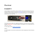
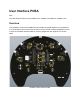
The TurtleBot 4 has a 2x20 pin internal connector connecting it to the Raspberry Pi via a flex
cable, and another 2x12 pin connector allowing the user to access the remaining GPIOs and a
set of 5V, and 3.3V power pins coming from the Raspberry Pi.
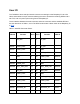
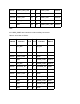
The IO interface between the 2x20 connector and 2x12 connector and the available GPIOs to
the user are shown in Table 1, and 2. The GPIO numbers are a direct match to the Raspberry Pi
4 GPIO.
Table 1: 2x20 RPi Connector Pinout
GPIO #
Function
Pin #
Pin #
Function
GPIO #
3V3_RPi
1
2
5V_RPi
GPIO2
USER_PORT
3
4
5V_RPi
GPIO3
USER_PORT
5
6
GND
GPIO4
SDA
7
8
USER_PORT
GPIO14
GND
9
10
USER_PORT
GPIO15
GPIO17
PWR_LED
11
12
MTR_LED
GPIO18
GPIO27
COMM_LED
13
14
GND
GPIO22
BATT_GRN_LED
15
16
BATT_RED_LED
GPIO23
3V3_RPi
17
18
WIFI_LED
GPIO24
GPIO10
USER_PORT
19
20
GND
GPIO9
USER_PORT
21
22
USER1_GRN_LED
GPIO25
GPIO11
USER_PORT
23
24
USER_PORT
GPIO8
GND
25
26
USER_PORT
GPIO7
GPIO0
EEPROM_SD
27
28
EEPROM_SC
GPIO1
GPIO5
SCL
29
30
GND