AP800 Audio Conferencing System Installation & Operation Manual
ii © 2002 ClearOne Communications, Inc. All rights reserved. No part of this document may be reproduced in any form or by any means without written permission from ClearOne Communications, Inc. Printed in the United States of America. ClearOne Communications, Inc. reserves specific privileges. Information in this document is subject to change without notice. AP800 Installation and Operation Manual ClearOne Part No. 800-150-001 July 2002 (Rev. 3.
iii AP800 Installation and Operation Manual Table of Contents CHAPTER 1: Introduction 1 Product Overview 1 Features 2 Professional Services Group 3 Technical Support 3 Sales and Customer Service 3 ClearOne Communications EuMEA GmbH 3 Product registration 3 Product returns 3 Unpacking 4 Controls and Connections 4 Front panel 4 Rear panel 5 G-Link Network 6 CHAPTER 2: Installation 7 Equipment Requirements 7 Power requirements 7 Auxiliary equipment 7 Equipment placement 7
iv Routing Parameters 24 Meter Parameters 27 CHAPTER 3: AP-Ware Software 29 Description 29 Installing AP-Ware 30 To install AP-Ware 30 CHAPTER 4: Operation 31 Control 31 Remote Control 31 Volume Control 31 Muting 32 APPENDICES 33 Appendix A: Specifications 33 Appendix B: Warranty 34 Appendix C: Compliance 35 Appendix D: Connector Pinouts 36 Appendix E: Accessories 38 Appendix F: Serial Commands 39 Appendix G: Worksheets 58 Glossary 61 Index 64 Technical Services Gro
CHAPTER 1: Introduction Product Overview Congratulations on purchasing the Audio Perfect® 800, an advanced twelve-bytwelve digital matrix mixer with Gentner® Distributed Echo Cancellation® and audio processing. It uses six user-definable presets to quickly adapt to a variety of teleconferencing and sound reinforcement applications such as distance learning, teletraining, telemedicine, courtrooms, conference rooms, boardrooms, hotels, and houses of worship.
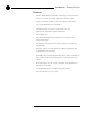
2 Introduction ~ Product Overview Features • Gentner® Distributed Echo Cancellation® technology; each microphone has its own echo canceller for a total of eight echo cancellers per unit • Easy-to-use AP-Ware software for quick configuration of all functions • 100 percent digital signal processing (DSP) • Simultaneous direct connection to several video codecs and telephone lines (using AP10 Telephone Interfaces) • 12x12 matrix mixer • Two internal submixing buses for mixing and level control in
Introduction ~ Professional Services Group Professional Services Group If you need any additional information on how to install, set up, or operate your system, please contact us at one of the locations listed below. We welcome and encourage your comments so we can continue to improve our products and serve your needs. ClearOne Communications ~ 1825 Research Way ~ Salt Lake City, UT 84119 Technical Support Telephone: 1.800.283.5936 (USA) or 1.801.974.3760 Fax: 1.801.977.0087 E-mail: tech.
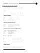
4 Introduction ~ Unpacking Unpacking ClearOne is not responsible for product damage incurred during shipment. You must make claims directly with the carrier. Inspect your shipment carefully for obvious signs of damage. If the shipment appears to be damaged, retain the original boxes and packing material for inspection by the carrier. Contact your carrier immediately. ! Ensure that the equipment shown below was received with your shipment. Optional www.gentner.
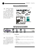
5 Introduction ~ Controls and Connections D. Meter. The Meter button takes you directly to the Meter branch of the AP800’s LCD programming tree. E. System, Inputs, Outputs, Routing. These buttons provide direct access to the corresponding sections in the LCD menu. F. Mic On LED. These LEDs indicate microphone gate status. A B D E F G C Rear panel Figure 1.3. Rear panel connections A. Power. This power module accommodates power ranging from 100–240VAC, 50/60Hz. No switching is required. B.
6 Introduction ~ G-Link Network G-Link Network G-Link network architecture allows up to eight AP800s/AP400s and up to 16 AP10 ✍ A G-Link network will allow interconnection of up to eight AP800s/AP400s and 16 AP10s. Telephone Interfaces to be controlled as if all were part of a single unit. Digital technology can provide a distinct advantage in designing and controlling teleconferencing systems.
CHAPTER 2: Installation Equipment Requirements Power requirements The AP800 will accommodate an AC voltage-input of 100–240VAC, 50/60Hz, 30W. Auxiliary equipment Any auxiliary equipment to be used with the AP800 (i.e., AP400, AP10 Telephone Interface, AP IR Remote Control, desktop kit, microphones, speakers, recording equipment, etc.) should be available at time of installation. Equipment placement The AP800 is designed for mounting in a 19" equipment rack.
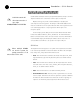
8 Installation ~ Installation Hardware Setup The AP800 is designed for easy installation and setup. All connections are made through rear-panel connectors. This chapter provides instructions on installing the units and making initial connections, creating a G-Link network, assigning device ID numbers, selecting the mixer mode, and using the LCD menu. The diagram below illustrates the typical connections that are made for a single-unit AP800 system.
9 Installation ~ Installation 3. If you are using an external RS-232 controller or the AP IR remote, connect it to the RS-232 port [F]. 4. Wire the inputs and outputs to the AP800 using the provided three-terminal Phoenix push-on connectors. These connectors are designed for easy wiring; simply insert the desired wire into the appropriate connector opening and tighten down the top screw.
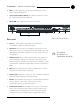
10 Installation ~ Installation AP800 unit 0 AP800 unit 1 G-Link Terminator AP800 unit 2 G-Link Terminator Figure 2.4. G-Link Network Connection To create a G-Link network 1. Insert a G-Link terminator (provided) in the G-Link In connector of the first unit in the network. 2. Connect the RJ-45 jumper cable (or Cat. 5 twisted-pair cable) to the G-Link Out connector of the first unit and to the G-Link In connector of the second unit. Continue connecting units in the same fashion. 3.
11 Installation ~ Installation Device types Device IDs are automatically assigned a device type. AP800s are always device type “1” (AP400 device types are “3”, AP10 device types are “2.”). The device ID # selected is added to the device type “3” to generate the unique address for that unit. For example, the first AP800 unit in your G-Link network would be identified as “10”, “3” being the Device Type, and “0” being the Device ID.
12 Installation ~ Installation To set mixer mode 1. Press the System button. Scroll through the menu until you see Mixer Mode. 2. Press Enter, then scroll through the three options. 3. Press Enter at the appropriate option to select it. 4. Repeat this process for all AP units in the G-Link network.
13 Installation ~ LCD Programming LCD Programming The AP800’s front panel is simple and intuitive to operate, thanks to its front-panel user interface: a 2x16 character LCD, previously described menu buttons, level LED bar meter and gate LED bar meter. When power is applied to the AP800, the LCD panel will first read INITIALIZING. If an error is displayed, contact technical support.
14 Installation ~ LCD Programming Power-Up Screen ClearOne AP800 Version X.X System Inputs Outputs Routing Meter Inputs Select Preset Inputs 1-8 Output 1-8 Route to Outputs 1-8 Lock Panel Inputs A,B,C,D Output A,B,C,D Set Passcode Subbus 1, 2 Outputs Route to Outputs A, B, C, D ERL Device ID Route to Subbus 1, 2 Default Meter Unit ID # Mixer Mode Gate Parameters ERLE Route to G-Link X,Y, Z Route to EC Reference 1, 2 RS- 232 Route to G-Link EC Ref Figure 2.6.
15 Installation ~ LCD Programming System parameters There are eight system-level parameters (see Figure 2.6, previous page) with which an AP800 can be programmed: select preset, lock panel, set passcode, device ID, unit ID number, mixer mode, gate parameters, and RS-232. For default settings, see the programming worksheet (page 59). Bolded items are the factory defaults. Select Preset The Select Preset menu item allows one of six presets to be selected for AP800 use.
16 Installation ~ LCD Programming A good way to remember the new passcode would be to create a word using the first letters of the buttons. For example, using Rooms as the passcode would be the key sequence: routing, output, output, meter, system. The passcode must be five characters long. Device ID The AP800’s device ID is set in the Device ID menu selection. There are eight G-Link network positions (0–7). See Device IDs, page 10.
Installation ~ LCD Programming Maximum Number of Mics This parameter sets the maximum number of microphones that can be gated on at any one time. This range can be set from one to eight microphones or off. The default setting is four. To set the maximum number of microphones, scroll through the number ranges (one through eight), select the desired number, and press Enter.
18 Installation ~ LCD Programming Figure 2.9. Off Attenuation Hold Time This feature determines the length of time that a microphone remains On after the microphone audio level drops below the gate ratio (Figure 2.10 below). Values range from 0.1–8.0 seconds in one-tenth second increments. Default setting is 0.3. Setting this value too low might cause the microphones to gate on and off too frequently during brief pauses of speech.
19 Installation ~ LCD Programming If your room has very low ambient noise, set the decay rate to fast. This reduces the effects of echo and reverberation. If you hear ambient noise “swoosh” down while the microphones decay, set this value to either medium or slow. Manual Ambient This setting is relevant only if the adaptive ambient mode is off on a mic channel (see Adaptive Ambient on page 22). The best results are usually achieved when the adaptive ambient mode is off.
20 Installation ~ LCD Programming Flow Control This parameter allows activation and deactivation of hardware flow control. The two options are on and off (default). To activate the flow control, scroll to on and press Enter. To deactivate it, scroll to off and press Enter. ✍ The init string can be set only with the MINIT serial command (see page 49) or AP-Ware software. It cannot be set through the front panel LCD.
21 Installation ~ LCD Programming Input Parameters There are three main submenus under the inputs menu tree: Inputs 1–8, Input Global; Inputs A, B, C, D; and Subbus 1–2. Inputs 1–8, Input Global The parameter submenus below this level control how an input channel deals with input audio. All parameters described can be applied to Inputs 1–8 or Input Global, which applies the selected parameters to all eight mic inputs. The thirteen mic input parameters are shown in Figure 2.13.
22 Installation ~ LCD Programming adjustment is +20dB, but will adjust only +6dB. Adjustments will not be made at .5dB on either side of the target (0dB). High Pass Filter A high-pass filter can be selected on each gated input to reduce unwanted noise. The filter has a break frequency at 250Hz, suppresses the signal 3dB at 200Hz, then rolls off at 6dB per octave below 200Hz. This feature is disabled when shipped from the factory.
23 Installation ~ LCD Programming AEC Reference There are two options for this parameter: EC Ref 1 and EC Ref 2. EC Ref 1 (default) references Output D (typically used for connection to a power amp and speaker). EC Ref 2 is not factory set. EC Ref 2 is typically used in soundreinforcement applications. This allows for the AP800 to provide two zones of sound reinforcement per AP800 unit. Echo Canceller Activate or deactivate the echo cancellation feature for each gated input. Factory default is on.
24 Installation ~ LCD Programming Output Parameters There are two main submenus under the outputs menu tree: Outputs 1–8 and Outputs A, B, C, D. The two main submenus each contain the same menus at the next menu depth: gain adjust, mute, and NOM (Figure 2.16). Each parameter is applied to the respective outputs (1–8 or A–D). Outputs 1–8, A–D Gain Adjust This adjusts each output’s gain (ranging between -20dB and 20dB).
Installation ~ LCD Programming Figure 2.18 Default routing matrix Routing Guidelines The audio matrix consists of sources and destinations. There are 25 possible input sources and 17 destinations. Internal Subbus Subbus 1, 2. The AP800 is equipped with two internal sub-mix buses. The subbus is a matrix output which allows signals to be mixed and level controlled. The subbus is then made available as an input to the matrix for further signal routing.
26 Installation ~ LCD Programming Echo Cancellation Setup Define EC Ref #1 Define EC Ref #2 Define G-Link EC Ref Bus Outputs A B C D 1 2 3 4 5 6 7 8 G-Link EC Ref Figure 2.19. Echo Cancellation Setup Default Matrix EC Reference bus This bus provides a system-wide echo canceller reference signal.
27 Installation ~ LCD Programming Echo Cancellation Setup Define EC Ref #1 Define EC Ref #2 Define G-Link EC Ref Bus Outputs A B C D 1 2 3 4 5 6 7 8 G-Link EC Ref Figure 2.21. EC Setup for Multiple Units to One Output (Slave Unit) Meter Parameters There are five main submenus under the meter menu tree: Inputs, Outputs, ERL, ERLE, and default meter (see Figure 2.22). The first four submenus are all handled in the same way.
28 Technical Services Group ~ 1-800-283-5936 (USA) ~ 1-801-974-3760
CHAPTER 3: AP-Ware Sof tware Description AP-Ware software is an all-new system software for Audio Perfect products. It replaces AP Tools software in ClearOne’s software line. AP-Ware provides increased configuration and system monitoring capabilities, and is straightforward to use. Virtually all AP800 functions can be configured with AP-Ware.
30 AP-Ware Software ~ Installing AP-Ware Installing AP-Ware To select an alternate destination directory, click Browse and use the Choose Directory window to find the desired location. Click OK to return to the previous window. To install AP-Ware 1. Boot the PC to the Windows operating system. Ensure that all other programs or applications are closed. Insert the Audio and Video Products CD into the CD-ROM drive. If the Autorun feature is enabled on the PC, the ClearOne Welcome window opens.
CHAPTER 4: Operation Control When operating the AP800, there should be very little to do with the AP800 unit itself. You can make changes quickly with AP-Ware software, if necessary. If correctly installed and programmed, the AP800 system should not require any further interface other than perhaps controlling volume of a particular output, or muting an input or output. Remote Control ClearOne Communications recommends use of a custom remote controller for user interface.
32 Operation ~ Control Muting To mute an input 1. Determine which input needs to be muted, then press the Inputs button. 2. Scroll through to the desired input channel, and press Enter. 3. Scroll through the input parameters until Mute is visible, then press Enter. 4. Use the s/t buttons to select On, then press Enter. The input is now muted. To unmute the input, follow the same procedure, but select Off to deactivate the mute function. To mute an output 1.
Appendices Appendix A: Specifications Dimensions (LxDxH) Weight Maximum Level: -33dBu, -4dBu, +20dBu Echo Cancellation: 120ms tail time (works with 12dB of room gain) Phantom Power: 24V, selectable 7 lb/4.5 kg dry 12 lb/5.9 kg shipping Line Inputs A-D 17.25" x 10.25" x 1.75" 43.8 x 26 x 4.
34 Appendices ~ Appendix B: Warranty Appendix B: Warranty ClearOne Communications, Inc. (Manufacturer) warrants that this product is free of defects in both materials and workmanship. Should any part of this equipment be defective, the Manufacturer agrees, at its option, to: A.
Appendices ~ Appendix C: Compliance warranty service performed on any product shall extend the applicable warranty period. In case of unsatisfactory operation, the purchaser shall promptly notify the Manufacturer at the address set forth below in writing, giving full particulars as to the defects or unsatisfactory operation.
36 Appendices ~ Appendix D: Connector Pinouts Safety Information CAUTION: Users should not attempt to make such connections themselves, but should contact the appropriate electrical inspection authority, or electrician, as appropriate.
Appendices ~ Appendix D: Connector Pinouts Control/Status B pinout Pin Number User Definable* Status Default Description 1 Yes C Preset 1 2 Yes S Status of Preset 1 3 Yes C Preset 2 4 Yes S Status of Preset 2 5 Yes C Preset 3 6 Yes S Status of Preset 3 7 Yes C Preset 4 8 Yes S Status of Preset 4 9 Yes C Mute Input A Toggle 10 Yes S Status of Input A Mute 11 Yes C Mute Input B Toggle 12 Yes S Status of Input B Mute 13 Yes C Mute Input C Toggle 14 Yes S
38 Appendices ~ Appendix E: Accessories RS-232 COM DCE Port Pinout 1 6 5 9 Pin Number 1 2 3 4 5 Control DCD TXD RXD DTR Ground Pin Number 6 7 8 9 Control DSR CTS RTS No connection Figure D.2.
Appendices ~ Appendix F: Serial Commands Appendix F: Serial Commands The AP800 accepts serial commands via the serial port; the commands are then channeled along the G-Link network to all interconnected AP products. The commands provide the same control as the LCD menu structure, plus several others. The following commands pertain only to the AP800.
40 Appendices ~ Appendix F: Serial Commands Note: Using the all-mic toggle might not produce the desired result, depending on the state the mics are in. For example, if one mic is muted and all other mics are not, an all-mic toggle would mute all others, but unmute that particular mic. Error Codes Error Error Error Error Error Error 1 2 3 4 5 6 The address is not valid/out of range or an invalid character. Could not extract a command from the string received. Serial overrun. Reserved. Invalid parameter.
41 Appendices ~ Appendix F: Serial Commands AAMB AGC This command changes or reports back the state of the adaptive This command changes or reports back the state of the AGC for ambient for a microphone. a microphone or line input.
42 Appendices ~ Appendix F: Serial Commands BAUD DECAY This command selects or returns the baud rate for the RS-232 This command changes or reports back the setting of the port on the AP800. decay rate for a given AP800.
43 Appendices ~ Appendix F: Serial Commands Return Values EC The command will return the updated condition (On=1, Off=0) of This command changes or reports back the state of the equalizer in the same format as the command. the echo canceller for a microphone. [DEVICE] EC Explanation ERL This command reports back the echo return loss (ERL) for a CH= 1-8 Parameter to apply to the specified mic channel microphone channel in dB.
44 Appendices ~ Appendix F: Serial Commands FMP This command selects or returns the status of the first FLOW microphone priority mode for the AP800. This command selects or reports whether hardware flow control [DEVICE] FMP is enabled or disabled for the AP800. Hardware flow control is implemented using RTS and CTS.
45 Appendices ~ Appendix F: Serial Commands GAIN GATE This command changes or reports back the input gain for a This command reports back the microphone gating status of channel. The command supports all inputs, outputs, and subbuses. an AP800. This command is read only.
46 Appendices ~ Appendix F: Serial Commands GMODE HOLD This command changes or reports back the gating mode for a This command changes or reports back the setting of the hold microphone. time.
47 Appendices ~ Appendix F: Serial Commands LMO MASTER This command changes or reports back the setting of the last This command selects or returns the current mode of the microphone on mode for each AP800. AP800 from the serial port.
48 Appendices ~ Appendix F: Serial Commands MDMODE MEQ This command enables or disables the modem mode for the This command changes or reports back the state of the AP800. When the modem mode is enabled, the modem equalizer adjustment for a microphone input. initialization string is sent out the serial port and the serial port now requires a password before a command is processed. [DEVICE] MEQ Note: The default password is a carriage return (enter).
49 Appendices ~ Appendix F: Serial Commands MHP MLINE This command changes or reports back the state of the high pass This command changes or reports back how much gain is filter for a microphone. applied to the microphone input. The three settings are 0dB, [DEVICE] MHP Explanation 25dB, and 55dB.
50 Appendices ~ Appendix F: Serial Commands MPASS MTRX This command sets the current password for modem mode. This command programs or reports the configuration of where Note: The default password is a carriage return (enter). If the an input is routed. The data is in a hex format. See the matrix password is forgotten, it can be cleared back to a carriage configuration table for specific routing information. return via the front panel.
51 Appendices ~ Appendix F: Serial Commands OUTPUTMIX=hex word. The selected input will be routed to the outputs indicated. OUTPUTMIX=null. Mix Command to return the current setting for the input. Note: When entering the hex value of the , it is not necessary to add the leading zeros, only zeros that follow the value, as in examples 1 & 2, below. Example 1 The following command routes Pregate Mic Input 1 audio to Output 1.
52 Appendices ~ Appendix F: Serial Commands MUTE NLP This command changes or reports the state of mute for a given This command changes or reports back the state of the channel. nonlinear processing for a microphone.
53 Appendices ~ Appendix F: Serial Commands NOM PAA This command changes or reports back state of NOM This command selects or returns the current status of the PA attenuation for each channel. adaptive mode.
54 Appendices ~ Appendix F: Serial Commands PCMD LOCATION=31 Control B pin 15 active LOCATION=32 Control B pin 15 inactive This command programs or returns the program of the GPIO control pins from the serial port. COMMAND can be any valid command. These values are not part of the preset and do not COMMAND=String Pin will execute string when change when presets are loaded.
55 Appendices ~ Appendix F: Serial Commands PEVNT EVENT=String Pin will execute string when actuated This command programs or returns the program of the GPIO EVENT=Null Parameter to return the current status pins from the serial port. The command line follows the programming for the pin same format as shown in the PCMD example above.
56 Appendices ~ Appendix F: Serial Commands PP REFSEL This command changes or reports back the state of the This command selects or returns the output to be used as the EC phantom power for a microphone. Reference 1 and EC Reference 2.
Appendices ~ Appendix F: Serial Commands UID This command returns the unique ID number, the device type and the device number of the AP800. This command is read only. The unique ID number is preprogrammed at the factory and is unique to the unit, while the device number is set by the user at the time of installation. [DEVICE] UID Return Values UID returns the device type, device number and unique ID number.
Define EC Ref #1 Define EC Ref #2 Define G-Link EC Ref Bus Echo Cancellation Setup A B Input A Input B Input C Input D G-Link X Bus G-Link Y Bus G-Link Z Bus Sub-bus S1 In Sub-bus S2 In Mic / Line 1* Mic / Line 2* Mic / Line 3* Mic / Line 4* Mic / Line 5* Mic / Line 6* Mic / Line 7* Mic / Line 8* Routing Matrix Setup O utputs G-Link S ub - b us C D 1 Outputs 4 2 3 5 *Inputs 1-8 6 7 8 O utpu t s G-Link EC Ref N = Non gated 2 3 4 5 6 7 8 G = Gated A B C D X Y Z S1 S2 1 58 Appendices ~ Ap
Technical Services Group ~ 1-800-283-5936 (USA) ~ 1-801-974-3760 Selection Range -20dB to 20dB (0) 0dB to -20dB (-6dB) Mic 55dB, Mic 25dB, Line Auto, Override On/Off, Manual On/Off On,Off On, Off On, Off On, Off On, Off -12dB to 12dB (0) -12dB to 12dB (0) -12dB to 12dB (0) On, Off On, Off 1, 2 On, Off Off, Soft, Medium, Aggressive Figure G.2.
On Off Mic / Line 1 Mic / Line 3 A/D Input Gain Line 55, 25 Mic On /Off Power Phantom On Off Mic / Line 4 A/D Input Gain Line 55, 25 Mic On /Off Power Phantom ECEA Nom On Off Filter On Off Mic / Line 5 A/D Input Gain Line 55, 25 Mic On /Off Power Phantom ECEA Nom On On Off On Off Mic / Line 6 A/D Input Gain Line 55, 25 Mic On /Off Power Phantom ECEA Nom Mute Gain Gain Off Output Output Mute D/A D/A (-12dB to +12dB) Off / Soft / Medium / Aggr
Glossary ~ A–D Glossary Acoustic Echo Cancellation (AEC) A process in which acoustical echo is removed from a signal. AEC can be used to remove unwanted signals from mic audio if the unwanted acoustic signal is available separately as an electronic signal. Adaptive Ambient Mode An automixing function that dynamically changes the ambient noise reference level based on a moving average of the actual noise floor of the room as picked up by the microphones.
62 Glossary ~ E–S Echo Cancellation The process in which acoustic echoes are canceled. This is accomplished by sampling the distant audio that is amplified through the loudspeaker in the room. When this audio is picked up by the microphone (this is acoustic echo), an echo canceller eliminates or “cancels” the echo. Equalization The enhancement of audio which can include high, low and band pass filtering. Equalization is used to filter out hum, noise, and other unwanted audio.
Glossary ~ T–Z Telephone Hybrid A term used to refer to a telephone interface that separates send and receive audio. Same as a digital hybrid. Two Wire Typically refers to a telephone line. Uni-directional Microphone A microphone that picks up audio in a directional (usually 180 degrees or less) pattern.
64 Index ~ A–Z Index A gate 15 adaptive ambient 19, 22 activation 21 ambient level 1, 41 auto-gate 21 AP-Ware 29 decay rate 18, 42 automatic gain control 1, 21, 23, 39 gate ratio 46 hold time 46 manual off 21 B manual on 21 baud rate 42 off attenuation 18, 53 PA adaptive mode 53 C Gentner Distributed Echo Cancellation 2 chairman override 42 GPIO 54, 55 clear password 20 command line 39 H connector pinouts 36 high pass filter 22 Control/Status B 37 I D Inputs 1-8 21 default meter