AP400 Audio Conferencing System Installation & Operation Manual
ii © 2002 ClearOne Communications, Inc. All rights reserved. No part of this document may be reproduced in any form or by any means without written permission from ClearOne Communications, Inc. Printed in the United States of America. ClearOne Communications, Inc. reserves specific privileges. Information in this document is subject to change without notice. AP400 Installation and Operation Manual ClearOne Part No. 800-150-001 July 2002 (Rev. 5.
iii AP400 Installation and Operation Manual Table of Contents CHAPTER 1: Introduction . . . . . . . . . . . . . . . . . . . . . . . .1 Product Overview . . . . . . . . . . . . . . . . . . . . . . . . . . . . . . . . . . . . . . . . . . .1 Features . . . . . . . . . . . . . . . . . . . . . . . . . . . . . . . . . . . . . . . . . . . .2 Professional Services Group . . . . . . . . . . . . . . . . . . . . . . . . . . . . . . . . . . .3 Technical Support . . . . . . . . . . . . . . . . . . . . . . . . . . . .
iv Input parameters . . . . . . . . . . . . . . . . . . . . . . . . . . . . . . . . . . . . . .23 Output parameters . . . . . . . . . . . . . . . . . . . . . . . . . . . . . . . . . . . . .26 Routing parameters . . . . . . . . . . . . . . . . . . . . . . . . . . . . . . . . . . . .26 Meter parameters . . . . . . . . . . . . . . . . . . . . . . . . . . . . . . . . . . . . .29 CHAPTER 3: AP-Ware Software . . . . . . . . . . . . . . . . . . . .31 Description . . . . . . . . . . . . . . . . . . . . . . . . . .
CHAPTER 1: Introduction Product Overview Congratulations on purchasing the Audio Perfect® 400, an advanced eight-by-eight digital matrix mixer with Gentner® Distributed Echo Cancellation®, audio processing, and a single-line telephone hybrid. It uses six user-definable presets to quickly adapt to a variety of teleconferencing and sound reinforcement applications such as distance learning, teletraining, telemedicine, courtrooms, conference rooms, boardrooms, hotels, and houses of worship.
2 Introduction ~ Product Overview Features • Distributed Echo Cancellation technology; each microphone has its own echo canceller for a total of eight echo cancellers per unit • Easy-to-use AP-Ware software for quick configuration of all functions • 100 percent digital signal processing (DSP) ensures crystal-clear audio with the deepest, most reliable hybrid null • Simultaneous direct connection to several video codecs • 8 x 8 matrix mixer • Internal submixing bus for mixing and level control i
Introduction ~ Professional Services Group Professional Services Group If you need any additional information on how to install, set up, or operate your system, please contact us at one of the locations listed below. We welcome and encourage your comments so we can continue to improve our products and serve your needs. ClearOne Communications ~ 1825 Research Way ~ Salt Lake City, UT 84119 Technical Support Telephone: 1.800.283.5936 (USA) or 1.801.974.3760 Fax: 1.801.977.0087 E-mail: tech.
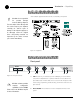
4 Introduction ~ Unpacking Unpacking Ensure that the equipment shown below was received with your shipment. ClearOne is not responsible for product damage incurred during shipment. You must make claims directly with the carrier. Inspect your shipment carefully for obvious signs of damage. If the shipment appears to be damaged, retain the original boxes and packing material for inspection by the carrier. Contact your carrier immediately. ! Audio Products www.gentner.
5 Introduction ~ Controls and Connections C. LED Meter. The LED bar meter is displays the audio level of any selected input or output on the AP400, as well as displaying echo return loss (ERL) and echo return loss enhancement (ERLE) for mic channels 1–4. D. Meter. The Meter button takes you directly to the Meter branch of the AP400’s LCD programming tree. E. System, Inputs, Outputs, Routing. These buttons provide direct access to the corresponding sections in the LCD menu. F.
6 Introduction ~ G-Link Networking D. Mics 1–4. Up to four mic/line-level inputs (selectable) can be connected using the three-terminal Phoenix connector(s). E. G-Link In, Out. These RJ-45 connectors are part of the AP400’s highspeed digital bus network, which passes audio between units. F. RS-232. This female DB-9 serial port is for connection between the AP400 and a PC, modem, or other custom remote control. For serial communications protocol, see Appendix E, page 43. G. Control/Status.
Introduction ~ G-Link Networking X-bus This mix-minus bus is defined as the master microphone mix, and it supports NOM (see page 26). All gated microphones are default routed to this bus. Y-bus This mix-minus bus is defined as the line input master mix. All line-level audio inputs such as video codecs, AP800s, AP10 Telephone Interfaces, VCRs, etc., are default routed to this bus. Y-bus does not support NOM. Z-bus This mix-minus bus is a user-defined auxiliary mix bus. Z-bus does not support NOM.
8 Technical Services Group ~ 1-800-283-5936 (USA) ~ 1-801-974-3760
CHAPTER 2: Installation Equipment Requirements Power requirements The AP400 will accommodate an AC voltage-input of 100–240VAC, 50/60Hz, 30W. Telephone line requirements The AP400’s telephone interface operates on a standard analog telephone line and connects with a standard RJ-11C modular jack. If you do not have an RJ-11C jack where you want to install the AP400, contact your telephone company for installation. Auxiliary equipment Any auxiliary equipment to be used with the AP800 (i.e.
10 Installation ~ Hardware Setup Hardware Setup The AP400 is designed for easy installation and setup. All connections are made through rear-panel connectors. This chapter provides instructions on installing the units and making initial connections, creating a G-Link network, assigning device ID numbers, selecting the mixer mode, and using the LCD menu. The diagram below illustrates the typical connections that are made for a single-unit AP400 system.
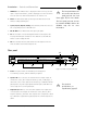
11 Installation ~ Hardware Setup Connecting the unit H A B D E I F G C To connect the AP400 1. Place the unit in a standard 19-inch rack and attach it securely. 2. Connect the telephone line from the wall jack to the RJ-11C Line jack [I]. 3. Plug the telephone set into the RJ-11C Set jack [I]. 4. If you are using a custom controller for control and status, connect it to the Figure 2.2. Rear panel connections Control/Status port [G].
12 Installation ~ Networking Units Networking Units A G-Link network supports connection of a maximum of any combination of 8 AP400s and AP800s. It also supports up to 16 additional AP10s, for a maximum of 24 telephone lines. ✍ G-Link connections Using the G-Link connectors, you can connect up to eight AP800/400s and 16 AP10 units, where the total number of microphone inputs does not exceed 64. Make connections between units in daisy-chain fashion using the short RJ-45 jumper (provided).
Installation ~ Networking Units Device IDs Once your physical G-Link network is established (and if you have more than one AP unit at a site), you need to specify unique device ID numbers for each AP400 on the network. As shipped from the factory, all AP400 units default as device ID “0”. Set device ID numbers for each unit at your site by manipulating the front-panel LCD. To set the device ID 1. Press the System button, then scroll to Device ID. 2.
14 Installation ~ Networking Units A system is defined as one or more AP units that communicate to perform mixing functions. A system can consist of one unit in master-single mode or several units that work together with one master-linked unit and multiple slave units. Systems can be G-Linked together for easy reconfiguration, as shown in Figure 2.5. The physical location on the G-Link network determines which system individual units belong to. In Figure 2.
15 Installation ~ LCD Programming LCD Programming For most installations, the default settings in the AP400 do not need to be changed; the system can be used as soon as power is applied. However, if you need to customize any settings, such as telephone connection options or unique routing requirements, you can do so through the front panel user interface or with AP-Ware software. The front panel includes a 2x16 character LCD, menu buttons, level LED bar meter and gate LED indicators.
16 Installation ~ LCD Programming ClearOne Figure 2.7. LCD menu tree Adjusting a value To adjust a parameter, first verify that it is flashing. If the parameter is not flashing, it cannot be adjusted. If the parameter is flashing, adjust the value with the ▲ and ▼ buttons. As the value is adjusted, the parameter is updated immediately. For example, if you adjust input gain, you should be able to hear the difference as it changes. To store the new value, press Enter.
17 Installation ~ LCD Programming System parameters The System button enables you to view and adjust nine parameters (see Figure 2.28): Select Preset, Lock Panel, Set Passcode, Device ID, Unit ID, Mixer Mode, Gate Parameters, RS-232, and Telco. For default settings, see the default programming worksheet (page 67). Items printed in boldface are the factory defaults. Select preset The Select Preset menu item allows you to select one of the six available preset configurations into the AP400.
18 Installation ~ LCD Programming A good way to remember the new passcode is to create a word using the first letters of the buttons. For example, using Rooms as the passcode would be the button sequence: Routing, Output, Output, Meter, System. Device ID The Device ID menu selection lets you choose from eight G-Link network IDs (0–7). See Device IDs on page 13. Unit ID ✍ When multiple AP400s are used in a system, the gate parameters on all units must be set the same.
19 Installation ~ LCD Programming Figure 2.9. PA Adaptive Mode First mic priority This feature helps maintain maximum audio intelligibility by allowing only one microphone to gate on when one person is speaking. ClearOne Communications recommends leaving this setting on. When turned off, usually two or more microphones gate on when only one person speaks. However, when this parameter is turned on, one person will usually be able to gate on only one microphone.
20 Installation ~ LCD Programming Figure 2.10. Off attenuation Off Attenuation This sets the amount of level reduction applied to a microphone when it is off (Figure 2.10, above). Low values increase the amount of echo and reverberation allowed into the system. If the value is set high, you might be able to hear the microphones gate on and gate off as the background noise is reduced. The adjustment range is from 0–50dB in 1dB increments. Default setting is 12dB.
21 Installation ~ LCD Programming Figure 2.12. Decay rate Decay Rate This feature determines how fast a microphone gates off after the hold time expires (see Figure 2.12). Three options are available for this feature: slow (default), medium, and fast. If your room has very low ambient noise, set the value to fast. This reduces the effects of echo and reverberation. If you hear ambient noise “swoosh down” while the microphones decay, set this value to either medium or slow.
22 Installation ~ LCD Programming RS-232 Five RS-232 parameters can be adjusted through the menu (see Figure 2.13). These parameters are baud rate, flow control, modem mode, and clear password. If data is lost during serial access through the RS-232 port, a serial overrun error will occur. This is indicated by flashing microphone LEDs. If the error is caused by incoming data, Meter LED “+12” flashes red; Meter LED “-10” and “Mic 4” flash green.
23 Installation ~ LCD Programming Telco The telephone interface can be set to automatically answer an incoming call (Auto Answer On), or allow the call to be handled manually (Auto Answer Off). The interface can also be set to disconnect upon Loop Drop, Call Progress, Loop Drop + CP (call progress), or to disconnect manually (Auto Disconnect Off). Input parameters There are three main submenus under the inputs menu tree: Input 1–4, Input A–D/Telco, and Subbus.
24 Installation ~ LCD Programming Phantom Power Each input will default with 24V phantom power enabled, but can be switched off to accommodate input devices not requiring phantom power. AGC Each input can use automatic gain control (AGC). This feature keeps softer and louder talkers at a consistent transmit level. This feature is disabled when shipped from the factory. The target gain is 0dB. It adjusts at 2dB per second. The AGC start adjustment is +20dB, but will adjust only +6dB.
25 Installation ~ LCD Programming Echo canceller Activate or deactivate the echo cancellation feature for each gated input. Factory default is on. NLP adjust Non-linear processing (NLP) has four settings: soft (6 dB), medium (12dB), aggressive (18dB), and off. NLP adds additional echo cancelling “horsepower” to the echo canceller in difficult acoustic environments. Care should be taken when using NLP because of the corresponding trade-offs, which can include suppression and half-duplex operation.
26 Installation ~ LCD Programming Output parameters There are two main submenus under the outputs menu tree: Output 1–4 and Output A–D/Telco Out. The two main submenus contain the same menus at the next menu depth: gain adjust, mute and NOM (Figure 2.18). Each parameter is applied to the respective outputs (1–4 or A–D/Telco Out). Output 1-4, Output A-D, Telco Gain adjust This adjusts each output’s gain (ranging between -20dB and 20dB).
27 Installation ~ LCD Programming Subbus The AP400 is equipped with one internal sub-mix bus. The subbus is a matrix output which allows signals to be mixed and level controlled. The subbus is then made available as an input to the matrix for further signal routing. Figure 2.20. Default routing matrix G-Link X-Z buses See page 7 for a description of this submenu. EC reference and PA The EC reference tells the microphones which output will be used as the sample reference for echo cancellation.
28 Installation ~ LCD Programming G-Link reference This bus provides a system-wide echo canceller reference signal. When multiple AP units are linked together and will be using only one output channel to drive the speaker system, that output must be defined as the sample reference which will be used by all of the linked AP units for echo cancellation. It allows the reference signal to be passed to additional G-Linked mic channels and their associated echo cancellers.
29 Installation ~ LCD Programming Meter parameters There are five main submenus under the Meter menu tree (Figure 2.24). Inputs, Outputs, ERL/TERL, and ERLE/TERLE The first four submenus are all handled in the same way. Using the LCD, press the Meter button, then scroll through the options (inputs, outputs, ERL/TERL and ERLE/TERLE) to specify which is to be metered by the front-panel LED meter. When the appropriate option is visible, press Enter to begin monitoring its status on the front-panel LED.
30 Installation ~ Worksheet Figure 2.25.
CHAPTER 3: AP-Ware Sof tware Description AP-Ware software is an all-new system software for Audio Perfect products. It replaces AP Tools software in ClearOne’s software line. AP-Ware provides increased configuration and system monitoring capabilities, and is straightforward to use. All AP400 functions can be configured with AP-Ware.
32 AP-Ware Software ~ Installing AP-Ware Installing AP-Ware To select an alternate destination directory, click Browse and use the Choose Directory window to find the desired location. Click OK to return to the previous window. ✍ To install AP-Ware 1. Boot the PC to the Windows operating system. Ensure that all other programs or applications are closed. Insert the Audio and Video Products CD into the CD-ROM drive. If the Autorun feature is enabled on the PC, the ClearOne Welcome window opens.
CHAPTER 4: Operation Front Panel A correctly installed AP400 virtually runs by itself. Typical operations involve changing volume of an output, muting an input or output, or handling calls on the connected telephone handset. For most installations, a custom remote control (optional) will be used. Controlling the volume When participating in a conference, you might find it necessary to increase or decrease the volume of a particular output.
34 Operation ~ Telco Interface The input is now muted. To unmute the input, follow the same procedure, but select Off to deactivate the mute function. To mute or unmute an output 1. Press the Outputs button, then scroll to the desired output channel. Press Enter. 2. Scroll through the output parameters until you see Mute. Press Enter. 3. Use the ▲ and ▼ buttons to select On, then press Enter. The output is now muted.
Operation ~ Controllers 3. Activate the telephone interface by clicking On or by beginning to dial. 4. Enter the number to be dialed, including any dial-out prefixes. 5. Click Send. If you clicked directly on the numbers, the call will be completed as you finish dialing—just like using a standard telephone. 6. When you are finished with the call, click Disconnect to end the call. Other telco options • Hook Flash. This feature sends a momentary interruption in line seizure to the telephone line.
36 Operation ~ Controllers Touch panel control The AP products are designed to function with touch panel control systems. The controller is connected to the AP400 RS-232 port. Through the G-Link network, all networked AP products can be accessed and controlled from that single point.
Appendices Appendix A: Specifications Dimensions (LxDxH) 17.25" x 10.25" x 1.75" 43.8 x 26 x 4.5 cm Weight 7 lb/3.18 kg dry 12 lb/5.4 kg shipping Operating Temperature 32–100° F/0–38° C Humidity 15% to 80%, non-condensing Power Input Range Auto-adjusting 100–240VAC; 50/60Hz Power Consumption 30W typical G-Link In/Out Proprietary Network RJ-45 (2), 38.
38 Appendices ~ Appendix B: Warranty and Compliance Appendix B: Warranty and Compliance Warranty ClearOne Communications, Inc. (Manufacturer) warrants that this product is free of defects in both materials and workmanship. Should any part of this equipment be defective, the Manufacturer agrees, at its option, to: A.
Appendices ~ Appendix B: Warranty and Compliance Manufacturer does not assume any responsibility for consequential damages, expenses, or loss of revenue or property, inconvenience, or interruption in operation experienced by the customer due to a malfunction in the purchased equipment. No warranty service performed on any product shall extend the applicable warranty period.
40 Appendices ~ Appendix B: Warranty and Compliance If this equipment causes harm to the telephone network, the telephone company will notify you in advance that temporary discontinuance of service might be required. If advance notice is not practical, the telephone company will notify the customer as soon as possible. Also, you will be advised of your right to file a complaint with the FCC if you believe it is necessary.
Appendices ~ Appendix B: Warranty and Compliance European Compliance (for international unit part no. 910-150-101 only) This equipment has been approved in accordance with Council Decision 98/482/EC for pan-European single terminal connection to the public switched telephone network (PSTN).
42 Appendices ~ Appendix C: Connector Pinouts Appendix C: Connector Pinouts RS-232 COM DCE port pinout Figure C.1. RS-232 connector Pin Number Control Pin Number Control 1 DCD 6 DSR 2 TXD 7 CTS 3 RXD 8 RTS 4 DTR 9 No connection 5 Ground Control/Status port pinout Figure C.2. DB-25 connector Pin # Definable* Status Moment./Latch.
Appendices ~ Appendix D: Accessories Status outputs: DB-25 female; open collector, 40V max, 300mA each (2) +5VDC, 300mA each 40V Control inputs: Input activation selectable; momentary or latching ground Appendix D: Accessories Accessory ClearOne Part Number AP800 910-150-001 AP10 Telephone Interface 910-150-201 Tabletop Omni Microphone 910-103-160 (with cable) Tabletop Uni Microphone 910-103-161 (with cable) Tabletop Omni Microphone 910-103-162 (black button)/ 910-103-163 (white button) Tabl
44 Appendices ~ Appendix E: Serial Commands Commands can be either uppercase or lower case. Return values are always in uppercase. For a command to be recognized by the serial port, the command must be terminated by a carriage return. For example, a command to disable automatic gain control (AGC) for Mic 2 on AP400 device “0” would have the command line: #30 AGC 2 0. In this command line, 3=AP400, 0=unit 0, AGC=command, 2=mic channel, 0=off state).
45 Appendices ~ Appendix E: Serial Commands The command string will then be explained (where necessary), followed by the returned values and (where necessary) an example. Figure E.1.
46 Appendices ~ Appendix E: Serial Commands Serial Command Parameters and AAMB Explanations This command changes or reports back the state of the adaptive ambient for a microphone. For serial port command protocol and syntax, see page 43. [DEVICE] AAMB Explanation AA This command activates and deactivates the auto answer CH= 1-4 feature.
47 Appendices ~ Appendix E: Serial Commands AD AGC This command changes the state of the auto disconnect function. This command changes or reports back the state of the AGC for a microphone or line input.
48 Appendices ~ Appendix E: Serial Commands AMBLVL BYE This command changes or reports back the setting of the This command immediately enables password protection when fixed ambient level for each AP400. This value is only used if modem mode is active. adaptive ambient is not enabled. [DEVICE] BYE [DEVICE] AMBLVL Note: This command is applicable only to the unit that is connected through the RS-232 port.
49 Appendices ~ Appendix E: Serial Commands DECAY DIAL This command changes or reports back the setting of the decay rate This command generates DTMF tones. The capability for a given AP400. remains active after the call is place so tones can be issued [DEVICE] DECAY for use with voice mail and pagers.
50 Appendices ~ Appendix E: Serial Commands EC ERLE This command changes or reports back the state of the echo This command reports back the echo return loss enhancement canceller for a microphone. (ERLE) for a microphone channel in dB.
51 Appendices ~ Appendix E: Serial Commands FLOW FPP This command selects or reports whether hardware flow control is This command sets and reports the current passcode setting enable or disabled for the AP400. Hardware flow control is for the AP400. implemented using RTS and CTS.
52 Appendices ~ Appendix E: Serial Commands GAIN GATE This command changes or reports back the input gain for a This command reports back the microphone gating status of an channel. The command supports all inputs, outputs, and subbus. AP400. This command is read only.
53 Appendices ~ Appendix E: Serial Commands GMODE HOLD This command changes or reports back the gating mode for a This command changes or reports back the setting of the microphone. hold time.
54 Appendices ~ Appendix E: Serial Commands HOOKD LMO This command controls and reports the Hook Duration of the This command changes or reports back the setting of the last unit. microphone on mode for each AP400.
55 Appendices ~ Appendix E: Serial Commands MASTER MEQ This command selects or returns the current mode of the AP400 This command changes or reports back the state of the from the serial port. equalizer adjustment for a microphone input.
56 Appendices ~ Appendix E: Serial Commands MHP MLINE This command changes or reports back the state of the high This command changes or reports back how much gain is pass filter for a microphone. applied to the microphone input. The three settings are 0dB, 25dB, and 55dB.
57 Appendices ~ Appendix E: Serial Commands MMAX MTRX This command changes or reports back the setting for the This command programs or reports the configuration of a maximum number of microphones on each AP400. routed input. The data is in a hex format. See the matrix [DEVICE] MMAX configuration table for specific routing information.
58 Appendices ~ Appendix E: Serial Commands OUTPUTMIX=hex word The selected input will be routed to the outputs indicated. OUTPUTMIX=null Mix Command to return the current setting for the input. Note: When entering the hex value of the , it is not necessary to add the leading zeros, only zeros that follow the value, as in examples 1 & 2, below. Example 1 The following command routes Pregate Mic Input 1 audio to Output 1.
59 Appendices ~ Appendix E: Serial Commands MUTE NLP This command changes or reports the state of mute for a given This command changes or reports back the state of the channel. nonlinear processing for a microphone.
60 Appendices ~ Appendix E: Serial Commands NOM OFFA This command changes or reports back state of NOM This command changes or reports back the setting of off attenuation for each channel. attenuation.
61 Appendices ~ Appendix E: Serial Commands PCMD state, the command returns the current command for which the pin is programmed. This command programs or returns the program of the GPIO control pins from the serial port. COMMAND can be any valid command. These values are not part of the preset and do not change when presets are loaded. Example The PCMD command line contains both the PCMD command and the command being programmed.
62 Appendices ~ Appendix E: Serial Commands PEVNT This command programs or returns the program of the GPIO status pins from the serial port. The command line follows the same format as shown in the PCMD example (previous page).
63 Appendices ~ Appendix E: Serial Commands PP REFSEL This command changes or reports back the state of the phantom This command selects or returns the output to be used as the power for a microphone. EC Reference and PA (speaker output).
64 Appendices ~ Appendix E: Serial Commands RING TAMODE This command reports the presence of a ring on the Telco port. This command controls or reports the Telephone Adapt Mode (This is an indication only.) control of the unit.
65 Appendices ~ Appendix E: Serial Commands TERL UID This command reports back the telephone echo return loss (TERL) This command returns the unique ID number, the device type for the AP400 in decibels. and the device number of the AP400. This command is read only. The unique ID number is preprogrammed at the factory [DEVICE] TERL and is unique to the unit, while the device number is set by Example the user at the time of installation.
66 Appendices ~ Appendix F: Worksheets Appendix F: Worksheets Figure F.1.
67 Appendices ~ Appendix F: Worksheets Figure F.2.
68 Appendices ~ Appendix F: Worksheets Figure F.3.
69 Index ~ A–O Index A activation 23 adaptive ambient 21, 23, 24 adaptive ambient 24 ambient level 1, 24 auto-gate 23 ambient noise 24 decay rate 18, 21, 49 AP-Ware 31 gate ratio 18, 53 automatic gain control 1, 10, 24, 25, 44 hold time 18, 53 manual off 23 manual on 23 B off attenuation 18, 20, 60 baud rate 22, 48 PA adaptive mode 18, 19, 60 GPIO 61, 62 C chairman override 24, 48 clear password 22 H high pass filter 56 command line 44 connector pinouts 42 Control/Status 42 I Inputs A-D
70 Index ~ P–Z P S password 22, 48, 55, 57 serial commands 43, 45 phantom power 23, 63 T telco 23, 25, 26, 64 R remote control 9 routing matrix 66 RS-232 1, 22, 24, 42, 43, 48 Gentner Technical Services Group ~ 1-800-283-5936 (USA) ~ 1-801-974-3760