
- ClearOne Communications Installation & Operation Manual Telephone Interface AP10


21
Technical Services Group ~ 1-800-283-5936 (USA) ~ 1-801-974-3760
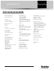
Set connector pinout
Pin Description Pin Description
1 To pin 6 of SET RJ-11C 4 Tip
2 To pin 5 of SET 5 To pin 2 of LINE
3 Ring 6 To pin 1 of LINE RJ-11C
Line connector pinout
Pin Description Pin Description
1 To pin 6 of LINE RJ-11C 4 Ring
2 To pin 5 of LINE 5 To pin 2 of SET
3 Tip 6 To pin 1 of SET RJ-11C
Appendices ~ Appendix B: Pinouts
Appendix C: Serial Commands
The AP10 accepts serial commands via the AP800’s serial port; the commands are
passed to the unit through the
G-Link network. The commands in this manual pertain only to the AP10. RS-232
serial port protocol is 9,600 (default), 19,200, or 38,400 baud; 8 bits, 1 stop bit,
no parity.
Conventions
The following typographic conventions are used in this document to describe the
different serial commands. Use the Command structure section and the examples as
a guide when creating your serial commands.