AP10 Telephone Interface Installation & Operation Manual
ii © 2002 ClearOne Communications, Inc. All rights reserved. No part of this document may be reproduced in any form or by any means without written permission from ClearOne Communications, Inc. Printed in the United States of America. ClearOne Communications reserves specific privileges. Information in this document is subject to change without notice. AP10 Installation and Operation Manual ClearOne Part No. 800-150-201 June 2002 (Rev. 2.
iii AP10 Installation and Operation Manual Table of Contents CHAPTER 1: Introduction . . . . . . . . . . . . . . . . . . . . . . . .1 Features . . . . . . . . . . . . . . . . . . . . . . . . . . . . . . . . . . . . . . . . . . . . . . . . .1 Professional Services Group . . . . . . . . . . . . . . . . . . . . . . . . . . . . . . . . . . .2 Product registration . . . . . . . . . . . . . . . . . . . . . . . . . . . . . . . . . . . .2 Product returns . . . . . . . . . . . . . . . . . . . . . . . . . . . . .
iv Receive Reduction . . . . . . . . . . . . . . . . . . . . . . . . . . . . . . . . . . . . .13 Calibration . . . . . . . . . . . . . . . . . . . . . . . . . . . . . . . . . . . . . . . . . . . . . . . .13 Noise Burst Adapt . . . . . . . . . . . . . . . . . . . . . . . . . . . . . . . . . . . . .13 Auto-Adapt . . . . . . . . . . . . . . . . . . . . . . . . . . . . . . . . . . . . . . . . . .14 Transmit level adjustment . . . . . . . . . . . . . . . . . . . . . . . . . . . . . . . .
CHAPTER 1: Introduction Congratulations on purchasing the Audio Perfect® telephone interface. The AP10 uses advanced digital technology to maintain the highest possible audio quality. The AP10 is designed as an accessory to the AP800 (echo cancelling, audio processing, microphone mixing matrix) and enables the AP800 to connect to a standard telephone line.
Introduction ~ Unpacking 2 Professional Services Group If you need additional information on how to install, set up, or operate your system, please contact us at one of the locations listed below. We welcome and encourage your comments so we can continue to improve our products and serve your needs. ClearOne Communications ~ 1825 Research Way ~ Salt Lake City, UT 84119 Technical Support Telephone: 1.800.283.5936 (USA) or 1.801.974.3760 Fax: 1.801.977.0087 E-mail: tech.support@clearone.
3 Introduction ~ Controls and Connections Unpacking ClearOne is not responsible for product damage incurred during shipment. You must make claims directly with the carrier. Inspect your shipment carefully for obvious signs of damage. If the shipment appears to be damaged, retain the original boxes and packing material for inspection by the carrier. Contact your carrier immediately. ! Ensure that the following items were received with your shipment: Figure 1.1.
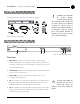
4 Introduction ~ Controls and Connections A C B D E F G Figure 1.3. AP10 rear-panel connectors Rear view A. Power. The AC power cord input is a NEMA-type connector allowing 100–240VAC, 50/60Hz. B. G-Link In, Out. This RJ-45 connector is used to connect the AP10 to the AP800 for control. AP-Ware is capable of accessing and controlling a G-Link local area network (LAN) of up to eight AP800/AP400 units and 16 AP10 units. G-Link supports a distance of up to 20 feet between each connected unit. C.
Introduction ~ Before You Install Before You Install Power requirements The AP10 automatically accommodates voltage requirements of 100–240VAC, 50/60Hz, 15W. Telephone line requirements The AP10 model operates on a standard analog telephone line and connects to the telephone system with a standard RJ-11C modular jack. If you do not have an RJ-11C jack where you want to install your AP10, call your telephone company for installation.
6 Technical Services Group ~ 1-800-283-5936 (USA) ~ 1-801-974-3760
CHAPTER 2: Installation The AP10 is designed for easy installation and set-up. All connections are made through rear-panel connectors. This section provides instructions on installing the units in the rack and making initial connections, creating a G-Link network, and assigning device ID numbers. The diagram below illustrates the typical connections that are made when adding an AP10 to an AP800.
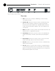
8 Installation ~ Hardware Setup A C B D E F G Figure 2.2. AP10 rear panel connectors 5. ✍ The three terminals in the Phoenix connector correspond with the backpanel audio contacts (from left to right): +(positive), –(negative), and (ground). + Wire the AP10 to the AP800 using the provided three-terminal Phoenix push-on connectors. These connectors are designed for easy wiring; simply insert the desired wire into the appropriate connector opening and tighten down the top screw.
9 Installation ~ Hardware Setup Assigning device ID numbers Once your physical G-Link network is established, you need to set up unique G-Link device ID numbers for each AP10 on the network. As shipped from the factory, all AP10 units default as binary address 0.
10 Technical Services Group ~ 1-800-283-5936 (USA) ~ 1-801-974-3760
CHAPTER 3: Configuration DIP Switch Settings The AP10 has a variety of operational features configurable through DIP switch settings, including noise burst/auto-adapt, receive AGC control, auto-answer, autodisconnect, call progression/loop, receive reduction, and hook-flash duration. Default settings (as shipped from the factory) are denoted by an asterisk “*”. Figure 3.1.
12 Configuration ~ DIP Switch Settings Receive AGC DIP switch 3 enables/disables the automatic gain control (AGC) function in the firmware. The AGC feature is designed to keep soft and loud telephone participants at a consistent level. DIP Switch Position Description 3* On (up) Receive AGC enabled 3 Off (down) Receive AGC disabled Auto-answer ✍ To issue the AA (autoanswer) serial command to toggle auto-answer, DIP switch 4 must be off (down). DIP switch 4 enables/disables auto-answer.
13 Configuration ~ Calibration Receive reduction In some applications, it might be necessary to duck (lower) the receive audio coming in through the telephone line when transmit audio is present. To enable receive reduction, set DIP switch 7 to the On position. DIP Switch Position Description 7 On (up) Receive reduction enabled 7* Off (down) Receive reduction disabled Calibration The following information will help you make adjustments to optimize your system performance.
14 Configuration ~ Calibration Auto-adapt If DIP switch 1 is off (down), call someone and continue to talk while the system gradually adapts over time. Once complete, the AP10 will be fully calibrated and ready for use. Press the Off button [E]. If the auto-disconnect feature is active, and the caller hangs up, the AP10 will disconnect upon sensing loop drop or callprogress tones, depending on the position of DIP switch 6.
CHAPTER 4: Operation The AP10 has four basic functions: make a call, answer a call, disconnect a call, and mute. This chapter explains how to perform these functions with the AP10 unit and a telephone handset (optional) and with the Telco interface in AP-Ware. You can also use touch panels and custom control devices. Using the AP10 A B C To answer a call D E Figure 4.1.
16 Operation ~ Using the Telco Interface 3. When the conversation is complete, press the Off button [E] to disconnect the call. You can also disconnect using an external controller. If the handset is off hook, audio will be routed to the telephone. If your call is through the handset only (the red Off LED will be lit), hang up when the conversation is complete. Using the Telco Interface To make and disconnect a call 1. Open AP-Ware and select the AP10 unit. 2.
Operation ~ Controllers To mute • Click Mute TX to mute the transmit audio (audio sent to the telephone line). • Click Mute RX to mute the receive audio (audio from the telephone line). Other telco options • Hook-Flash. This button sends a momentary interruption in line seizure to the telephone line. • Re-Null. This feature sends a short noise burst down the telephone line and forces the AP10 to adapt to the telephone line. • Auto-Answer. This button turns auto-answer on and off.
18 Technical Services Group ~ 1-800-283-5936 (USA) ~ 1-801-974-3760
APPENDICES Appendix A: Specifications Dimensions (LxDxH) 17.25" x 10.25" x 1.75" 43.8 x 26 x 4.5 cm Weight 7.5 lb/3.4 kg dry 12.6 lb/5.
20 Appendices ~ Appendix B: Pinouts Appendix B: Pinouts 13 25 Figure B.1.
21 Appendices ~ Appendix B: Pinouts Set connector pinout Pin Description Pin Description 1 To pin 6 of SET RJ-11C 4 Tip 2 To pin 5 of SET 5 To pin 2 of LINE 3 Ring 6 To pin 1 of LINE RJ-11C Line connector pinout Pin Description Pin Description 1 To pin 6 of LINE RJ-11C 4 Ring 2 To pin 5 of LINE 5 To pin 2 of SET 3 Tip 6 To pin 1 of SET RJ-11C Appendix C: Serial Commands The AP10 accepts serial commands via the AP800’s serial port; the commands are passed to the unit through
22 Appendices ~ Appendix C: Serial Commands Convention Description Parameters enclosed in < > indicate a mandatory parameter. [X] Parameters enclosed in [ ] indicate an optional parameter. 1-8 Parameters separated by a - indicate a range between the values. 4,7,9 Parameters separated by a , indicate a list of available values. EREF Words in uppercase bold indicate command text. DEVICE Indicates the device type and device number on the G-Link network.
Appendices ~ Appendix C: Serial Commands AP10 Serial Commands Command Function AA Sets auto-answer for a telco channel DIAL Dials a DTMF sequence or reports last sequence dialed HOOK Sends a hook flash to the telephone line LVL Reports the level of the transmit or receive channel (read only) MUTE Sets the mute for the transmit or receive channel NULL Re-nulls the AP10 to the telephone line RING Ring acknowledgement TE Selects/reports the connect state of the unit TERL Reports the telco e
24 Appendices ~ Appendix C: Serial Commands Return values: DIAL returns the dialed string of numbers. The string is returned after the command has been completed (i.e. dialed all the touch tones). Example: The following command dials the number (801) 975-7200. A 9 and a pause is generated to get an outside line on a PBX. The number is to be dialed on device #20.
Appendices ~ Appendix C: Serial Commands LVL This command reports back the transmit or receive level for a unit. Command form: DEVICE LVL Explanation: is which parameter to be measured. CH=RXIN CH=RXOUT CH=TXIN CH=TXOUT Parameter for level from the telephone line Parameter for level from the AP10 Parameter for level into the AP10 Parameter for level to the telephone line Return values: LVL will return the output level of the line channel in the same format as the command.
26 Appendices ~ Appendix C: Serial Commands NULL This command sends a short noise burst down the telephone line and forces the AP10 to adapt to the telephone line. This command is write-only. Command form: DEVICE NULL Return Values: If the renull succeeded, the following is returned: DEVICE NULL RING When the AP10 receives a ring at the dialed-up location, the AP10 will respond: Device RING TE Controls and reports the connection status of the unit.
Appendices ~ Appendix C: Serial Commands TERLE This command reports back the telephone echo return loss enhancement (ERLE) for the AP10 in dB. This is a read-only parameter. Command form: DEVICE TERLE Return values: If the current TERLE level for the telephone canceller is 20dB, the following is returned out the serial port: DEVICE TERLE 20 UID This command returns the unique ID number of the unit. This command is read-only. Command form: DEVICE UID Return values: UID returns the unit ID code.
28 Appendices ~ Appendix D: Warranty Appendix D: Warranty ClearOne Communications, Inc. (Manufacturer) warrants that this product is free of defects in both materials and workmanship. Should any part of this product be defective, the Manufacturer agrees, at its option, to: A.
Appendices ~ Appendix D: Warranty Manufacturer shall not be liable for punitive, consequential, or incidental damages, expenses, or loss of revenue or property, inconvenience, or interruption in operation experienced by the end user due to a malfunction in the purchased product. No warranty service performed on any product shall extend the applicable warranty period.
30 Appendices ~ Appendix E: Compliance Appendix E: Compliance FCC Part 15 Compliance This equipment has been tested and found to comply with the limits for a Class A digital device, pursuant to Part 15 of the FCC rules. These limits are designed to provide reasonable protection against harmful interference when the equipment is operated in a commercial environment.
Appendices ~ Appendix E: Compliance If you experience problems with this equipment, contact ClearOne Communications, Inc., 1825 Research Way, Salt Lake City, Utah 84119, or by phone at (801) 975-7200 for repair and warranty information. If the trouble is causing harm to the telephone network, the telephone company might request that you remove the equipment from the network until the problem is resolved. No user serviceable parts are contained in this product.
32 Appendices ~ Appendix F: Block Diagram Appendix F: Block Diagram G–LINK RS-485 CNVRT Technical Services Group ~ 1-800-283-5936 (USA) ~ 1-801-974-3760
Glossary Glossary Acoustic Echo Cancellation (AEC) A process in which acoustical echo is removed from a signal. AEC can be used to remove unwanted signals from mic audio if the unwanted acoustic signal is available separately as an electronic signal. Ambient Noise The existing room-level noise, such as that caused by ventilation systems, paper shuffling, and background chatter. Attenuation A reduction of signal amplitude.
34 Glossary Matrix mixer A mixer that allows routing of any input or combination of inputs to an output or any combination of outputs. Omni-directional Microphone A microphone that picks up audio in a 360-degree pattern. Reverberation Audio in a room that bounces off a wall, ceiling, table or other objects and then is picked up by microphone. High reverberation causes listener fatigue and makes audio difficult to understand.
35 Index Index A H answer a call 15 hook-flash 17, 24 AP-Ware 15, 16 hook-flash duration 11, 24 AP10 3 connecting the unit 7 control 17 features 2 L line connector 21 loop drop 11, 12, 14 front-panel controls 3 operation 15 rear-panel connectors 4 auto-adapt 11, 13, 14 auto-answer 3, 11, 12, 15, 17, 23 auto-disconnect 11, 12, 15 M make a call 15, 16 meter 17 mute 15, 17, 25 N C calibration 13 call progression 11, 12, 14 control 17 noise burst 11, 13, 26 null 26 P pinouts 17, 20 D device ID 7
36 Index T telco echo cancellation 2, 19 Telco interface 15, 16 telco line 4 telco set 4 TERL 26 TERLE 27 tip and ring 4 transmit input 4, 8, 19 transmit LED 3, 9 transmit level 14, 25 V version 27 W white noise 11, 13 Technical Services Group ~ 1-800-283-5936 (USA) ~ 1-801-974-3760