
Manual


C7420 Fiber C/Port Installation • 21
Understanding C7420 LED Indicators
The following lists detail the LED indicators on the front and rear of the C7420.
Front Panel
• Blue power indicator—Illuminated when the
C7420
is powered on.
• Link LED—Shows when a connection, or link, is established between the
C7420
and a
blade.
– Green LED—C/Port and blade are connected.
– Red LED—C/Port and blade are not connected (for example, the
C7420
LC fiber
optic cable is disconnected).
Rear Panel
• ACT/LOS—This LED indicates fiber activity and a loss of signal.
– Blinking green—Signal activity
– Orange—Loss of fiber signal
• SPD—This LED indicates connection speed. When illuminated, a 100–megabit
connection is established.
Configuring the C7420 Fiber C/Port
ClearCube A1410 and R1350 PC blades contain V5120 Dual Host cards connected to the
blade’s PCI Express® connector. V5120 cards and C7420 Fiber C/Ports contain PCoIP
processors that manage video and audio data. When configuring and working with a C7420
user port connected to a blade with a V5120 Dual Host card, remember that:
• There are two PCoIP processors:
– C7420 Fiber C/Port processor
– V5120 Dual Host card processor
• Each PCoIP processor has an IP address, for a total of two IP addresses
You must provision PCoIP processors on blades and on user ports when deploying C7420
Fiber C/Ports. To provision a C7420, you must:
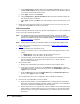
1. Determine the IP address structure for your environment and determine the IP addresses of
the blade, the V5120 Dual Host card, and the C7420 Fiber C/Port.
2. Provision the PCoIP processors on the C7420 and on the blade that connects to the user
port.
3. Establish a network connection between the C7420 and a blade using any of the following
options:
– Direct cable connection or connection through local Ethernet switch
– DHCP connection
– ClearCube Sentral®
The following section describes the default network address settings that the C7420 Fiber
C/Port and V5120 Dual Host use.