C/Port and Multi Video Expander User’s Guide
Technical Support Please refer to our support website for technical updates, additional warranty information and documentation, and software revisions: Web: http://support.clearcube.com Email: support@clearcube.com Phone: (512) 652-3400 or call toll free (866) 652-3400 (United States) ClearCube Technology Corporate Headquarters Mailing and Shipping Address: The ClearCube Building 8834 Capital of Texas Hwy N. Austin, Texas 78759 Email: info@clearcube.
Contents Preface . . . . . . . . . . . . . . . . . . . . . . . . . . . . . . . . . . . . . . . . . . . . . . . . . . . . . . . . . . . . . . . . . . . . . . . . . . . . . . . vii How to Use this Guide . . . . . . . . . . . . . . . . . . . . . . . . . . . . . . . . . . . . . . . . . . . . . . . . . . . . . . . . . . . . . . . vii FCC Warning . . . . . . . . . . . . . . . . . . . . . . . . . . . . . . . . . . . . . . . . . . . . . . . . . . . . . . . . . . . . . . . . . . . . . .
C7420 Fiber C/Port Installation . . . . . . . . . . . . . . . . . . . . . . . . . . . . . . . . . . . . . . . . . . . . . . . . . . . . . . . . . . . . Setting up the C7420 Fiber C/Port . . . . . . . . . . . . . . . . . . . . . . . . . . . . . . . . . . . . . . . . . . . . . . . . . . . . . . . Understanding C7420 LED Indicators . . . . . . . . . . . . . . . . . . . . . . . . . . . . . . . . . . . . . . . . . . . . . . . . . . . Configuring the C7420 Fiber C/Port . . . . . . . . . . . . . . . . . . . . . .
Declaration of Conformity . . . . . . . . . . . . . . . . . . . . . . . . . . . . . . . . . . . . . . . . . . . . . . . . . . . . . . . . . . . . .45 C7420 Fiber C/Port and F6150–160 Fiber Transceiver . . . . . . . . . . . . . . . . . . . . . . . . . . . . . . . . . . . . . . . . . .46 ElectroMagnetic Compatibility (EMC) . . . . . . . . . . . . . . . . . . . . . . . . . . . . . . . . . . . . . . . . . . . . . . . . . . . .46 Emissions (Radio Frequency Interference) . . . . . . . . . . . . . . . . . . . . .
vi
Preface How to Use this Guide Thank you for purchasing your quality ClearCube products. The ClearCube Architecture was developed to bring you unprecedented levels of manageability, security, reliability, and space savings. The ease of use of ClearCube’s products makes installation straightforward. This manual provides all the product and installation information needed to set up and run ClearCube Technology’s C/Port Architecture for managed desktop environments.
ClearCube Technology is committed to meeting the requirements of the European Union WEEE Directive and is currently developing country-specific implementation plans that comply with the WEEE legislation. The goal of the directive is to reduce the environmental impact due to the disposal of electrical and electronic equipment that has reached the end of its useful service life. This directive goes into enforcement on August 13, 2005.
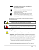
Fuse Located on equipment rating label. Symbol is accompanied with the specifications needed for replacement. Only qualified technicians should perform this operation. Protective Earth Terminal Identifies the terminal that is used to connect all metal parts of the enclosure through an external conductor to ground for the protection against electrical shock in a fault condition. Equipment Protection Class II May be located on the power adapter’s rating label.
• • • • • • • equipment is put into service. Please refer to the installation sections of this manual for specific power cord requirements. For replacement of power cords, refer to Appendix C – Technical Support. Power Adapters – ClearCube or ClearCube’s Distributors provides power adapters that are specifically designed for use with that particular piece of equipment and are approved for use by the local authority having jurisdiction in the country where the equipment is put into service.
Chapter 1. ClearCube C/Port Overview The ClearCube architecture delivers Intel-based PC functionality to the desktop from a secure, centralized location. This results in dramatic increases in manageability and security while providing mission-critical reliability, performance, and uptime improvements with lowered costs. Replacing a traditional PC box with a ClearCube C/Port or I/Port in an office or cubicle also saves space, eliminates fan noise and simplifies cabling resulting in a clear cube.
Figure 1. ClearCube C/Port C/Ports are connected via standard twisted-pair copper networking cables: CAT5, CAT5e, CAT6, or CAT6e. Table 1 lists the distance limits for C/Port installations. Table 1. C/Port Connection Limits Cable Type Distance CAT5 660 feet (200 meters) CAT5e 660 feet (200 meters) CAT6 * CAT6, CAT6e C7130: 330 feet (100 meters) ** C7120 or earlier: 330 feet (100 meters) C7130: 660 feet (200 meters) certified for 45 nS / 100 meters delay skew or less.
Fiber Solution This section describes: • C7420 Fiber C/Port • F6150–160 fiber transceiver C7420 Fiber C/Port The C7420 is connected to an F6150–160 fiber transceiver, and the fiber transceiver is connected to ClearCube PC blades. When deployed using a secure point-to-point fiber connection, data displayed to the desktop does not commingle with any network traffic, and users cannot disconnect the fiber desktop for use with a PC or notebook. C7420 does not require special OS drivers.
Front Link Indicator Power Indicator LED USB 1.1 Ports Power Button Rear DVI–I Port 1 Power Connector Fiber Activity DVI–I Port 2 Audio In LC Fiber Audio Out USB 1.1 Ports Remote Blade Power Button Figure 2. C7420 Fiber C/Port For more information about setting up your C7420, about connecting devices to the C7420, and about understanding the indicator LEDs, see "C7420 Fiber C/Port Installation" on page 20.
Multi-Video Expander The ClearCube Multi-Video Expander (MVX) provides a revolutionary way to multi-task and process information. While the C/Port provides all the peripheral and USB connections, the multiplexed video signal can be passed through to the MVX via a noise-limiting VGA connector cable. The MVX distributes the individual video frames to the appropriate output connectors. The two video outputs on the MVX are special, high-density connectors that can each drive two monitors.
Cable Requirements The ClearCube chassis uses standard network cables with RJ45 connectors to connect to C/Ports and to an Ethernet network. These can be CAT5, CAT5e, CAT6, or CAT6e cables. C/Ports require straight-through cables with all four twisted pairs available. See Table 1 on page 2 for a maximum distance chart for these cables for C/Ports. Network connections follow standard Ethernet guidelines.
The following figure shows a typical cabling configuration to connect C7420 Fiber C/Ports to an A3100 chassis. Note the recommended configuration, where the data network is separated from the PCoIP network. Sentral Server Sentral Switch A3100 Chassis with 10 A1410 Blades PCoIP .... PRI SEC BLADE 5 PCoIP PRI .... SEC BLADE 6 External Data Sources and Entities Network Switch Data Network Fiber Transceiver Fiber Connections C7420 Fiber C/Ports and Peripherals Figure 5.
8 • ClearCube C/Port Overview
Chapter 2. C/Port Installation Caution Statements Improper connection, mounting, or use of this product could result in component failure or undesired interference. Read the following caution statements before setting up and operating your C/Port. Setup • • • • Do not connect to AC power until all other connections are made, including the power adapter.
C7130 and C7120 C/Port Installation The model C7130 C/Port provides automatic sharpness tuning that simplifies installation. When connected to an R4300 chassis, the C7130 also provides a color Auto-tune feature that greatly simplifies initial video configuration on the desktop. Previous C/Ports require manual sharpness and color configuration on all chassis models. C7130 C/Ports also require manual color configuration when connected to R4200 chassis models, but provide automatic sharpness tuning.
Identifying your Chassis R4300 and R4200 chassis can easily be identified in your data center. Figure 6 on this page shows R4300 and R4200 chassis. Note the difference in the connectors on the lower apron. Figure 6. R4300 Chassis (L) and R4200 Chassis (R) Unpacking the C/Port The C/Port package contains one of each of the following items: • • C/Port unit C/Port power supply and power cord A special tuning tool for adjustments is included with the documentation and software package in your shipment.
Power Indicator (Blue Light Around Badge) DC Power Input Blade Connection (RJ-45) Video Sharpness Adjustment Dial Video Output C/Port Link Status (Green = link, Red = no link) Microphone Input USB (2 Ports) Keyboard Port Audio Output Blade Reset/Power Button Mouse Port Figure 7.
A C 8 4 2 0 6 C7130 Auto-Tune Default Setting (F, not marked) C7130 E 8 0 6 C A E 4 2 C7130 Manual Tune Setting (1, not marked) Figure 8. C7130 C/Port Color Switches 4 6 2 8 0 C7110 / C7120 C/Port Default Setting (1, not marked) Universal C/Port II C7110 Figure 9. C/Port Color Switches, Earlier Versions 2. Locate your C/Port in a ventilated area away from any heat sources.
Do not attach the C/Port to a telephone jack or other powered network connection. This will permanently damage the C/Port. This damage is not covered under the ClearCube Technology limited warranty. 6. Connect the C/Port power supply module to the C/Port power input, and then plug the power supply into the AC power socket. Make sure you have the properly rated power supply module for your local power outlet. The blue power indicator on the left side of the C/Port will light. 7.
Figure 10. ClearCube C/Port Tuning Guide Before Tuning a C/Port Download the ClearCube C/Port Tuning Guide, Tuning a C7130 Connected to an R4300 Chassis A C7130 connected to an R4300 performs Auto-tuning for both sharpness and color. In most cases, no further adjustment is required. However, a small amount of fine-tuning is possible. Do the following: 1. Open the ClearCube C/Port Tuning Guide (downloadable from the ClearCube Technology Support Web site and shown in Figure 10 on page 15).
2. Change the three color tuning switches from position F to position 1. The colors should be in better alignment. 3. View the black-and-white test patterns. Adjust the Video Sharpness control for the clearest picture. 4. View the color bar patterns. Beginning with the color bar that is the farthest to the left, turn the color switches one click at a time until the vertical color bars are in the best alignment. 5. If desired, fine-tune the C/Port. See “Fine-Tuning Model C7130 C/Ports” on page 16.
On the C7130, when color alignment is complete on a fine-tuned automatic alignment, all three switches must be in position E or F. For a manually tuned system, at least one switch must be in position 0 or 1. If these conditions are violated, the colors will be mis-aligned until the switch positions are corrected. Tuning Notes Fiber C/Ports do not require any tuning. Any C/Port, whether Auto-tunable or not, can be tuned manually by starting at switch positions 1-1-1.
Locking out Mass Storage Devices An additional feature provides increased levels of security with C/Ports. The R Series PC blades offer a unique Mass Storage Lockout (MSL) security feature that disables the use of any USB mass storage device at the desktop (e.g., key drives, floppy drives, CD-ROM drives, etc.).
JP6 1 3 JP6 Default Setting: USB Mass Storage devices function normally 1 3 Security Setting: USB Mass Storage devices will not function JP6 Figure 12. Model R1300 MSL Jumper Location and Settings JP6 1 JP6 JP6 Default Setting: USB Mass Storage devices function normally 3 1 3 Security Setting: USB Mass Storage devices will not function Figure 13.
C7420 Fiber C/Port Installation ClearCube C7420 Fiber C/Ports connect to ClearCube A1410 and R1350 PC blades to provide the following features: • LC fiber optic connector • Support for one or two independently–configurable monitors • PC–over–IP™ (PCoIP™), delivering PC video and audio over your IP network • Four USB 1.1 ports • HD audio in and audio out Setting up the C7420 Fiber C/Port 1. Place your C7420 on a desk or use the included mounting bracket to mount the C7420. 2.
Understanding C7420 LED Indicators The following lists detail the LED indicators on the front and rear of the C7420. Front Panel • Blue power indicator—Illuminated when the C7420 is powered on. • Link LED—Shows when a connection, or link, is established between the C7420 and a blade. – Green LED—C/Port and blade are connected. – Red LED—C/Port and blade are not connected (for example, the C7420 LC fiber optic cable is disconnected).
Understanding Default Network Addresses The C7420 Fiber C/Port and V5120 Dual Host are initially configured for DHCP connections. If a DHCP server does not provide an IP address within 20 seconds of startup, the C7420 and the V5120 use the default network addresses detailed in the following table. Table 3. Default Static Addresses C7420 Fiber C/Port IP Address 192.168.1.100 255.255.255.0 192.168.1.1 192.168.1.101 Subnet Mask Gateway Address Peer Address V5120 Dual Host 192.168.1.101 255.255.255.0 192.
1. Ensure that you have connected devices as described in “Setting up the C7420 Fiber C/Port” on page 20. 2. Connect the chassis and C7420 Fiber C/Port. a. Connect one end of a CAT5 or CAT6 Ethernet cable to the appropriate port on your chassis. • R4300 chassis—Insert the cable in the Secondary Network port. • A3100 chassis—Insert the cable to the PCoIP port. b.
f. Click Configuration > Session. Ensure that the Accept Any Peer option is clear. In the Peer MAC Address line, type the MAC address of the C7420 (the MAC address is on a label on the bottom of the C7420). g. Click Apply and then click Continue. h. Click Configuration > Monitor Emulation. Select the monitor emulation option for both monitors (DVI 1 and DVI 2). i. Click Apply and then click Reset. The V5120 displays a power state message. Click OK. 5.
c. From the Tera1200 PCoIP Processor menu, click Configuration > Monitor Emulation. Select the monitor emulation option for both monitors (DVI 1 and DVI 2). d. Click Apply and then click Continue. e. Click Configuration > Discovery and select the Enable Discovery option. f. Click Apply to save your changes and a success message is displayed. Click Reset and then click OK to reset your blade and apply your changes. g. Close the browser. 5.
26 • C/Port Installation
Chapter 3. MVX Installation Hardware Installation Installing the Video Adapter If you ordered your multi-video system pre-configured, see “Software Installation and Configuration” on page 29. If you are updating a single-monitor blade to add multi-video functionality, follow the procedure on the installation sheet that accompanies your Quadro4 video card. After installing the card, power up the blade and click Cancel when prompted by the New Hardware Wizard to install software.
Figure 16. MVX Connection Diagram Note: The monitor connector ends of each splitter cable are stamped with either a 1 or a 2 to indicate the output sequence order. The Multi-Video Solution supports several different resolutions and refresh rates. Table 4 lists the supported combinations. These combinations apply per monitor, with all monitors set to identical resolutions and refresh rates. Table 4.
Once the C/Port has been installed and the blade has been powered up, the user needs to fine tune the video image by choosing the desired resolution, selecting the refresh rate that looks best, and using the tuning dial on the rear of the C/Port to sharpen the video image appropriately. In addition, color tuning may be required using the color switches on the bottom of the C/Port, as described in the C/Port Installation chapter.
Figure 17. Removing the Old NVIDIA Drivers 7. Click Change/Remove and Yes at the next prompt to remove the currently installed NVIDIA drivers. 8. Click OK to restart the computer. A default video driver in Windows provides video support for your monitor. Installing the NVIDIA Driver Download and install the latest NVIDIA-supplied driver from the ClearCube web site at support.clearcube.com. Note: 1. 2. 3. 4.
Figure 18. Display Settings Tab 5. Set the resolution to 1280 x 1024 (not all flat panel monitors support resolutions greater than 1024 x 768) pixels and click Apply. Click OK if prompted. 6. Click the Advanced button and then select the Monitor tab, shown in Figure 19. ClearCube recommends that the screen refresh rate be set to 60 Hz for flat-panel monitor use, or 75 Hz for CRT use.
Figure 20. Quadro NVS Tab 8. On the side window, click ClearView. Figure 21 shows the resulting screen and the default 1x1 display configuration. Figure 21. Default 1x1 Monitor Configuration 9. In the Select Display Configuration menu, select the configuration that matches the physical layout of the monitors and click Apply. The recommended Preferred Display Refresh rate is 3x.
10. Click Desktop Utilities in the ClearView side window. Figure 22. Quadro NVS Tab 11. Click the Enable Desktop Manager check box, click Apply, and click the Desktop Manager Configuration button. The Desktop Management tab, shown in Figure 23, is displayed. Figure 23. Desktop Management Tab 12. Click the Enable nView Desktop Manager check box, click Apply, and then click the Wizard button. This launches the NVIDIA Desktop Manager Setup wizard. 13.
optimized for use with ClearCube Multi-Video equipment. Individual settings can be changed if desired. Figure 24. Profiles Screen 14. Continue with the remaining screens to customize desktop and user interface options. Important Notes about MVX The LED indicator on the front bezel of the MVX provides useful link status information. A green status light indicates the MVX is receiving a good video output signal from the C/Port.
• • • The video sharpness and color switch settings on the C/Port apply to all monitors. In Windows XP, changing display settings causes a brief video flicker as the MVX adjusts to the video signal from the blade more frequently than necessary. This behavior can also occur when the operating system is starting up or shutting down. The tuning dial on the C/Port is very sensitive. Rapid movements may cause loss of the video signal momentarily.
36 • MVX Installation
Appendix A. Troubleshooting If you have any problems with your system, please check the following items prior to calling for support. C/Ports Red link status indicator on PC blade and C/Port • • • • • Check cables for correct pin-out, which is the same as for standard Ethernet over CAT5 cable. Check that all wire pairs are terminated properly.
Loss of peripheral devices (USB) • • Unplug and re-plug-in the devices. Pull blade out and re-insert. No video or link lights at desktops and no power to blades • • R4300: Have a qualified service technician check the fuse. R4200: Check the chassis AC fuse. MVX No video is present • • • Turn the manual adjust knob on the back of the C/Port. The video signal can be cut off when the manual adjustment knob is turned fully clockwise or counter-clockwise.
3. Select Enable VGA Mode and press the Enter key. 4. Once booting completes, set the display to a supported setting and restart the system. Mouse movement is slow or sluggish • • Increase the Preferred Display Refresh in the ClearView settings. Increase the mouse pointer speed level by adjusting the mouse pointer settings via the Windows control panel.
support@clearcube.com Email address to ClearCube Technical Support support.clearcube.com ClearCube Support Web site support.clearcube.
Appendix B. Specifications C/Port Table 6. C/Port Specifications • • • Connections Dimensions • • • • • • • Environment • Max Distance • • • NOTE: Power Adapter • • VGA monitor connection (standard DB-15) RJ-45 for PC blade connection Requires full CAT5-type cable with all four pairs connected straight through 2 powered USB 1.1 Ports PS/2 Mouse and Keyboard Ports Audio Out (34 ohm headset or amplified speaker system required) Audio In 1.3"H x 5.1"D x 7.
C7420 Fiber C/Port Table 7. C7420 Fiber C/Port Specifications Dimensions Operating System Fiber Type Connector Type Distance Video Connections Power Connection Power Supply Shipping Weight Environmental Approximately 1.6–inches H x 9.5–inches W x 5.2–inches D None 62.
Appendix C. Regulatory Compliance C/Port and MVX ElectroMagnetic Compatibility (EMC) The statements contained within this section are limited to the C/Port and MVX. Regulatory compliance specifications for any other equipment mentioned within this manual can be found in separate documentation.
• • • • EN 61000-4-5: 1995, Surge Immunity Requirements, performance criteria: 2/1 kV EN 61000-4-6: 1996, Conducted Disturbance Induced by Radio-Frequency Fields Immunity, performance criteria: 3 Vrms EN 61000-4-8: 1994, Power Frequency Magnetic Field Immunity, performance criteria: 1 A/m EN 61000-4-11: 1994, Voltage Dips, Short Interruptions and Voltage Variations Immunity, performance criteria: 95%-5c and 250c, 30%-25s Power Harmonics and Flicker Other requirements that this equipment has been found to
Declaration of Conformity Manufacturer: ClearCube Technology, Inc.
C7420 Fiber C/Port and F6150–160 Fiber Transceiver ElectroMagnetic Compatibility (EMC) The statements contained within this section are limited to the C7420 Fiber C/Port and F6150–160 fiber transceiver. Regulatory compliance specifications for any other equipment mentioned within this manual can be found in separate documentation.
Power Harmonics and Flicker Other requirements that this equipment has been found to comply with are: • EN 61000-3-2: 1995, Limits for Harmonic Current Emissions (equipment input less than or equal to 16 A per phase) • EN 61000-3-3: 1995, Limitation of Voltage Fluctuations and Flicker in Low Voltage Supply Systems for Equipment with rated Current = 16 A Safety Compliance The C7420 was tested and is certified to the following safety standards: • UL 60950 • CAN/CSA-C22.2 No.
Safety: • EN60950:2000 • EN60825-1:1994 +A1+A2 (Laser Class 1 Product) EMC: • EN55022:1998 • EN55024:1998 • EN61000-4-2:1995 • EN61000-4-3:1996 • EN61000-4-4:1995 • EN61000-4-5:1995 • EN61000-4-6:1996 • EN61000-4-8:1993 • EN61000-4-11:1994 • EN61000-3-2 • EN61000-3-3 This product is in conformity with the requirements of the Low Voltage Directive (73/23/EEC) and the EMC Directive (89/336/EEC). Signed, Rick Hoffman, CEO ClearCube Technology, Inc.
P/N G020075 Rev B