
User guide


20
PG2-MADI-F-FX User Guide
9.3 Hardware Connection
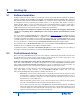
An exemplary network with four devices is shown in Fig. 1. It is established by creating a (non-redundant) loop
simply through "daisy-chaining" the units and monitoring the three status LEDs of each device, as revealed through
the signal flow in diagram. There is no need to worry about the sequence of neither IDs nor which of the two LINKS
of a device is used for connection. The only condition is that an optical input must be connected to an optical output.
During the self-configuring of the network the system word clock master will be automatically determined as
indicated down under ProGrid Network Setup – General . If the PG2-MADI-F-FXs and other ProGrid devices are
previously configured, the network is ready to work. With a PC connected to any unit in the loop and by running the
OPTOCORE CONTROL software, the network may be analyzed, supervised, parameters may be changed and the
matrix can be accessed for signal-routing.
Fig. 1: A non-redundant network with one PG2-MADI-F-FX unit
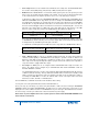
A second redundant reverse loop can be additionally created with only one more connection from the last unit of the
chain back to the first, as demonstrated by the signal flow diagram in Fig. 2.
Fig. 2: A redundant network with one PG2-MADI-F-FX unit
In case an interruption occurs at position “a” as illustrated above, this will only result in a loss of redundancy. This
also applies to the very unlikely case of a device failure. The redundancy of the ring can be reestablished simply by
connecting the in and out fiber with the help of an adapter and a new device can be integrated at any time.