
User guide


19
PG2-MADI-F-FX User Guide
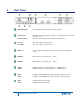
Clock Setup: All devices in the network must work with the same sample rate. CLOCK SOURCE allows
the selection of Auto (BNC priority), INT (internal) or BNC (external) word clock signal.
RS485 Ports: The RS485 SETUP is used to define, which signal is given out at the specific port of the
device. There are 32 data channels available in the network. It is necessary to allocate physical inputs
as the 4-channel bank. Four output it is possible to choose one of 32 channels per each port.
To illustrate the setting of the ports in OPTOCORE CONTROL a configuration with a PG2-MADI-F-FX at
FOH and a PG2-MADI-F-FX on stage will be used as an example. The PG2-MADI-F-FX at FOH with
ID 1 will transmit control data to an external device at Port 3 and receive data at Port 4. The PG2-MADI-
F-FX with ID 2 on stage will transmit control data to an external device at Port 3 and receive data at
Port 4 as well. Accordingly the data received at ID 2 / Port 4 has to be transmitted by ID 1 / Port 3 to the
data port of the external devices at FOH. This is the return path from the stage devices to the FOH
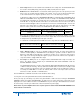
device. In order to enable this connection the RS485 SETUP of the FOH device with ID 1 is:
In
(which channel data is transmitted to)
Out
(which channel is received for each port)
Port
Channel 1-4
Port 3 / Channel 8
RS485
None of the other RS485 Out Ports have to be adjusted and can be disabled. The definition of the ports
as DISABLED only declares that they are not used as outputs. Data received at the disabled ports will
be transported to any destination by the fiber optic connection.
To establish the command path from the FOH device to the stage device the RS485 SETUP of ID 2 is:
In
(which channel data is transmitted to)
Out
(which channel is received for each port)
Port
Channel 5-8
Port 3 / Channel 4
RS485
Video / Ethernet setup: In order to use ProGrid for Ethernet transport, the option System Ethernet
should be enabled globally. In PG2-MADI-F-FX Local Setting it is possible to enable or disable Local
Ethernet as well. While System Ethernet is enabled it is possible to use only the first video channel.
Video setup can be done by allocating video input in a proper channel. This channel can be outputted on
every device which is equipped with video output.
Port Setup: The MADI ports can be configured under PORT SETUP while locally connected to the
device. The settings can be changed only in OFFLINE Mode with LOCAL SETTINGS or with the
ACTION / SEND ALL command.
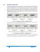
The PORT SETUP allows the selection of the appropriate AES10-Standard (AES10-2003 (64 channels)
or AES10—1991 (56 channels)). This only defines the maximal number of channels, the actually needed
number of channels is appointed for each port separately. The LEDs on the font indicate the setting. If,
for example, the MADI INPUT 1 receives 16 channels, LED 1 and 2 of the input section are lit. If 56
Channels are read in, the LEDs 1-7 will indicate this.
Click on WRITE first, confirm with OK, and then click CLOSE to exit the dialog.
You may now connect the optical LINK cables between all ProGrid devices.
Check your setup by connecting to any device using either RS232 or USB connection, running the OPTOCORE
CONTROL software and starting ONLINE MODE in the SET menu. The entire network at its current state is now
displayed in the control software. Check the LOG WINDOW for any error messages. All ProGrid devices memorize
the current setup, even if they are switched off or disconnected from the power supply.
Never switch on power amplifiers before the complete system is stable and the OPTOCORE CONTROL level
meters indicate a normal level.