PG2-MADI-F-FX User Guide PN: 399G089 Rev A 05/19/14
Document Reference Clear-Com PG2-MADI-F-FX User Guide Part Number: 399G089 Revision: A Legal Disclaimers Copyright © 2014 HME Clear-Com Ltd. All rights reserved. Clear-Com and the Clear-Com logo are registered trademarks of HM Electronics, Inc. The software described in this document is furnished under a license agreement and may be used only in accordance with the terms of the agreement.
Contents Document Reference......................................................................................................... 2 1 Important Safety instructions ....................................................................... 5 1.1 Safety symbols ................................................................................................ 6 2 Device Description ........................................................................................ 7 3 Front Panel ....................
9 Starting Up................................................................................................... 18 9.1 Software Installation ...................................................................................... 18 9.2 ProGrid Network Setup ................................................................................. 18 9.3 Hardware Connection.................................................................................... 20 9.4 Network Examples ............................
1 Important Safety Instructions Read these instructions. Keep these instructions. Heed all warnings. Follow all instructions. Do not use this apparatus near water. Clean only with dry cloth. Do not block any ventilation openings. Install in accordance with the manufacturer’s instructions. Do not install near any heat sources such as radiators, heat registers, stoves, or other apparatus (including amplifiers) that produce heat. Do not defeat the safety purpose of the polarized or grounding-type plug.
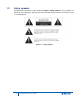
1.3 Safety symbols Familiarize yourself with the safety symbols in Figure 1: Safety symbols. These symbols are displayed on the apparatus and warn you of the potential danger of electric shock if the system is used improperly.
2 Device Description Optocore TECHNOLOGY Optocore™ is a technology platform for sending large amounts of audio, with very low latency around a fiber-based network. This transport (and management system) is of very high quality, suitable for concerts, recording studios, and broadcast applications. SANE™ is a spin-off technology that adapts this same technique to a smaller network (Ethernet) and at a lower cost. The SANE connections are used to provide expansion units at any fiber node.
Due to SMD production the PG2-MADI-F-FX fulfills the demand of highest digital standards occupying only one rack unit of a 19" rack. The FPGA (field programmable gate array) based concept of the internal logic circuitry permits updating of the hardware by the use of the units remote ports, ensuring a continual state-of-the-art device. OPTOCORE CONTROL software is used to change the configuration or define own settings.
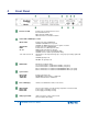
3 Front Panel Word Clock LED: Indicates the selected word clock source: INT: Internal word clock BNC: External via BNC Input NET: Word clock received from network Status LEDs of MADI Input 1 and 2: INPUT SYNC OUTPUT ON MADI 56 / 64 1/2/3/4/5/6/7/8 Indicates the status of MADI Input LED ON: Valid MADI frame is present LED OFF: No MADI signal is present or signal is not valid Indicates the status of MADI Output Indicates if there is MADI protocol active MADI format and number of channels LED ON: 64 CH
RS232 plug: D-Sub-9 RS232 connection for remote control and update via PC LAN LINK: Indicates the Ethernet link status S1: Ethernet communication is established via SANE 1 (rear panel) S2: Ethernet communication is established via SANE 2 (rear panel) There is other device with physical Ethernet port enabled on the network L1: Ethernet communication is established via LAN 1 (rear panel) L2: Ethernet communication is established via LAN 2 (rear panel) Sample Rate LED: Indicates the selected sample rate 4
4 Rear Panel RS485/GPIO plug: D-Sub-9 RS485 AUXILIARY PORT for data transmission Word Clock IN: Word Clock OUT: BNC Word clock input allows synchronization of ProGrid devices to an external word clock source BNC Word clock output for synchronization of external devices Video IN: Video OUT: BNC Video input for composite video BNC Video output for composite video MADI 1 / 2: 2 x SC multimode optical MADI inputs and 2 x SC multimode optical MADI outputs POWER 2: Mains input for power supply 2 (100 …
5 Device Details 5.1 Fiber Optic Connection The ProGrid Signal Transport Solution uses a digital Time Division Multiplex technology (TDM) with a fiber channel based 8B10B-NRZI-coding. Static time slots guarantee the synchronous transmission of all channels at any time with no demand for dynamic bandwidth. All signals attached to the audio, video, word clock and auxiliary ports of the device are transmitted simultaneously on one fiber. The second fiber of one LINK-Interface is used to receive data.
The word clock outputs are used for the synchronization of external devices with digital I/Os such as preamps, controllers and consoles. All connected devices with digital I/Os have to get the word clock from the ProGrid device with which they exchange digital audio data. The ProGrid network is used to distribute the word clock. 5.6 Video Ports A video in- and output is integrated for the transmission of composite video signals. 5.
6 Control All system and device parameters are set on a PC connected to the device via RS232 or USB port by use of the OPTOCORE CONTROL software. Third party protocols for device controlling can be used, if previously adapted by ProGrid.
7 Channel Allocation The standard channel allocation for 2 Gbit network is as follows: Audio 768 Channels @48 KHz RS485 Data 32 Channels Video 3 CVBS Video Channels * Ethernet 100 MBit Fast Ethernet * * If the network is used for the transport of Ethernet compatible data the capacity is reduced to one CVBS video channel plus 100 Mbps Fast Ethernet.
8 Connectors and Cables 8.1 Optical Connection The dual optical LINK-interfaces are equipped with duplex LC connectors. The PG2-MADI-F-FX is equipped with standard SFP transceivers which can be changed by the user. Standard LC cables with two fibers can be used. Worst case reach is 700 m with multimode transceivers and a 50 m fiber, whilst with monomode transceivers and a 9 m fiber, up to 70 km are possible. For rugged applications e.g.
8.8 Word Clock-Connection Use 75 -coaxial-cable with BNC-connectors. 8.9 Video-Connection Use 75 -coaxial-cable with BNC-connectors. 8.10 Mains-Connection Standard power cords with IEC C13 socket can be used.
9 Starting Up 9.1 Software Installation Installation requirement for the software is a functioning computer system with Microsoft Windows 2k (Requires installation of GDIplus.dll), XP 32&64Bit, Vista 32&64Bit, Server2003&2008, Windows7 32&64Bit or Mac: Intel based Macs with above OS using Bootcamp/Parallels/VMWare. The computer should be equipped with an USB interface for configuration and remote controlling, and a RS232 interface (or an appropriate USB / RS232 converter) for firmware upgrade. COM 1...
Clock Setup: All devices in the network must work with the same sample rate. CLOCK SOURCE allows the selection of Auto (BNC priority), INT (internal) or BNC (external) word clock signal. RS485 Ports: The RS485 SETUP is used to define, which signal is given out at the specific port of the device. There are 32 data channels available in the network. It is necessary to allocate physical inputs as the 4-channel bank. Four output it is possible to choose one of 32 channels per each port.
9.3 Hardware Connection An exemplary network with four devices is shown in Fig. 1. It is established by creating a (non-redundant) loop simply through "daisy-chaining" the units and monitoring the three status LEDs of each device, as revealed through the signal flow in diagram. There is no need to worry about the sequence of neither IDs nor which of the two LINKS of a device is used for connection. The only condition is that an optical input must be connected to an optical output.
9.4 Network Examples Fig.
Fig. 4: Redundant network with one PG2-MADI-F-FX and four PG16-FX devices.
10 Connection Tables Pin-out Auxiliary Ports 4 x RS485 RS485 Channel GND 1 2 3 4 + 1 2 3 4 - 6 7 8 9 Pin Please assure correct polarity “+” and “-“ at both (!) sides / devices when connecting external equipment to the RS485 ports. 5 5 1 D-Sub-9- female Locking system acc.
PG2-MADI-F-FX Auxiliary Port 4 x RS485 X3...
11 Technical Specifications MADI Ports Convention AES10-1991 / AES10-2003 Inputs Number / Connectors 2 / optical MADI digital audio channels 56 or 64 per Input Number / Connectors 2 / optical MADI digital audio channels 56 or 64 per Output Outputs Data rate 125 Mbps Output/Input Output 1310 nm (typical) Max.
12 Dimensions and Weight Front panel: width 483 mm / 19 inch height 44 mm / 1.73 inch depth 200 mm / 7.87 inch Rear panel: width 438 mm / 17.25 inch Weight 2.7 kg ≡ 4.41 lbs Modifications that serve the purpose of technical improvement of the device may be carried out without prior notification.
13 Compliance FCC notice This device complies with Part 15 of the FCC rules. Operation is subject to the following two conditions: (1) This device may not cause harmful interference, and (2) This device must accept any interference received, including interference that may cause undesired operation. NOTE: This equipment has been tested and found to comply with the limits for a Class A digital device, pursuant to Part 15 of the FCC rules.
recovery from municipal collection points, reuse, and recycling of specified percentages per the WEEE requirements. Instructions for Disposal of WEEE by Users in the European Union The symbol shown below is on the product or on its packaging which indicates that this product was put on the market after August 13, 2005 and must not be disposed of with other waste.
14 Installation Warning: For Electromagnetic Compliance, this product must be assembled to a grounded rack or cabinet using a split-ring lock washer or star washer with appropriate screws, nuts, or bolts.
15 Warranty and Liability The Clear-Com product that you have purchased is covered by the Clear-Com Standard Limited Warranty, the terms and conditions of which can be found at www.clearcom.com/support/warranty-support-policies. We encourage you to review the Standard Limited Warranty to determine its coverage, exclusions from coverage and duration.