FREESPEAK DIGITAL WIRELESS INSTRUCTION MANUAL Version 2.0.
FreeSpeak Instruction Manual © 2007, 2008, 2009 Vitec Group Communications Ltd. All rights reserved. Part Number 810340Z Rev. 8 Vitec Group Communications LLC 850 Marina Village Parkway Alameda, CA 94501 U.S.A Vitec Group Communications Ltd 7400 Beach Drive IQ Cambridge Cambridgeshire United Kingdom CB25 9TP The Vitec Group plc Beijing Representative Office Room 706, Tower B Derun Building, YongAn Dongli A No.3 Jianwai Ave., Chaoyang District Beijing, P.R.
Vitec Group Communications SOFTWARE LICENSE IMPORTANT: CAREFULLY READ THE FOLLOWING BEFORE USING THIS SOFTWARE. USING THE SOFTWARE INDICATES YOUR ACKNOWLEDGMENT THAT YOU HAVE READ THE FOLLOWING AND AGREE TO ITS TERMS. IF YOU DO NOT AGREE, RETURN THE SOFTWARE COMPLETE TO VITEC GROUP COMMUNICATIONS LIMITED OR CANCEL THE INSTALLATION. THIS IS YOUR PROOF THAT YOU HAVE A VALID LICENSE. PLEASE TREAT IT AS VALUABLE PROPERTY. VITEC GROUP COMMUNICATIONS LIMITED OR VITEC GROUP COMMUNICATIONS, INC.
copyrights, trademarks or other intellectual property. VGC and its licensors retain all right, title and interest in and to the Software and all copies thereof at all times, regardless of the form or media in or on which the original or other copies may subsequently exist. This license is not a sale of the original or any subsequent copy. 2. COPYRIGHT a. The copyright and all other rights in the Software produced by VGC shall remain with VGC or its suppliers.
b. After the initial 90 days, THE SOFTWARE IS PROVIDED "AS IS" WITHOUT WARRANTY OF ANY KIND EITHER EXPRESS, IMPLIED OR STATUTORY, INCLUDING BUT NOT LIMITED TO THE IMPLIED WARRANTIES OF MERCHANTABILITY, FITNESS FOR A PARTICULAR PURPOSE, PERFORMANCE, ACCURACY, RELIABILITY, OR NON-INFRINGEMENT OF THIRD-PARTY INTELLECTUAL PROPERTY RIGHTS. This constitutes an essential part of this License. 7. LIMITATION OF LIABILITY: a.
other rights) and only a duly executed written release shall constitute such a waiver. b. If any of these conditions is deemed invalid or unenforceable the remainder shall be unaffected. c. VGC's dealings with you shall be governed by English law if you are resident in the EMEA region and California law if you are resident elsewhere.
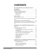
CONTENTS GETTING STARTED: AN INTRODUCTION TO FREESPEAK . . . . . . . . . . . . . . . . . . . . . . . . . . . . . . 1-1 FreeSpeak Features . . . . . . . . . . . . . . . . . . . . . . . . . . . . . . . . . . . . . 1-2 A FreeSpeak Communication System . . . . . . . . . . . . . . . . . . . . . . . 1-3 Important Installation Information . . . . . . . . . . . . . . . . . . . . . . . . . 1-5 System Password . . . . . . . . . . . . . . . . . . . . . . . . . . . . . . . . . . . 1-5 Default Map . . . . . . . . . . .
Stage Announce Output Connector. . . . . . . . . . . . . . . . . . . . . . 4-2 Stage Announce Relay . . . . . . . . . . . . . . . . . . . . . . . . . . . . . . . 4-3 4-Wire Matrix Ports . . . . . . . . . . . . . . . . . . . . . . . . . . . . . . . . . . 4-3 Base Loop Connector (not used). . . . . . . . . . . . . . . . . . . . . . . . 4-3 LAN Connector . . . . . . . . . . . . . . . . . . . . . . . . . . . . . . . . . . . . . 4-3 PC Connector . . . . . . . . . . . . . . . . . . . . . . . . . . . . . . . . . .
Using the Basestation’s Programming Menus . . . . . . . . . . . . . . . . . 5-2 Saving Changes . . . . . . . . . . . . . . . . . . . . . . . . . . . . . . . . . . . . . . . . 5-2 Basestation Password . . . . . . . . . . . . . . . . . . . . . . . . . . . . . . . . . . . 5-2 Changing Beltpack Labels . . . . . . . . . . . . . . . . . . . . . . . . . . . . . . . . 5-4 Setting and Changing Port Labels . . . . . . . . . . . . . . . . . . . . . . . . . . 5-6 Setting and Changing Group Labels. . . . . . . . . . . .
Left and Right Scroll Buttons . . . . . . . . . . . . . . . . . . . . . . . . . . . 6-4 Enter/Answer-Back Button. . . . . . . . . . . . . . . . . . . . . . . . . . . . . 6-4 Beltpack Batteries . . . . . . . . . . . . . . . . . . . . . . . . . . . . . . . . . . . . . . . 6-5 Beltpack Rear/Battery Section . . . . . . . . . . . . . . . . . . . . . . . . . . . 6-5 Power Button . . . . . . . . . . . . . . . . . . . . . . . . . . . . . . . . . . . . . . . 6-5 Battery Case . . . . . . . . . . . . . . . . . . . . .
PROGRAMMING AT THE BELTPACK . . . . . . . . . . 7-1 Introduction to Programming on the Beltpack. . . . . . . . . . . . . . . . . . 7-1 Beltpack Programming - Menu Structure . . . . . . . . . . . . . . . . . . . . . 7-1 Main Programming Menu . . . . . . . . . . . . . . . . . . . . . . . . . . . . . . . . . 7-2 The Alarm Options Menu . . . . . . . . . . . . . . . . . . . . . . . . . . . . . . . . . 7-3 Switching the Low Battery Alarm ON and OFF . . . . . . . . . . . . . . . 7-4 Low Battery Alarm Off . . . . .
Transceiver/Antenna Setup Rules and Tips . . . . . . . . . . . . . . . . . 8-4 Transceiver/Antenna Splitter (PD2203) . . . . . . . . . . . . . . . . . . . . . . 8-5 PD2203 Front Connector Panel . . . . . . . . . . . . . . . . . . . . . . . . . . 8-6 Basestation Connection Indicator Light . . . . . . . . . . . . . . . . . . . 8-6 Matrix (FreeSpeak Basestation) Connector. . . . . . . . . . . . . . . . 8-6 Splitter-to-Transceiver/Antenna Signal Indicator Light . . . . . . . 8-6 Transceiver/Antenna Connectors .
Exit. . . . . . . . . . . . . . . . . . . . . . . . . . . . . . . . . . . . . . . . . . . . . . 10-5 Uploading configurations Using the Serial Link. . . . . . . . . . . . . . 10-6 Uploading configurations Using Ethernet . . . . . . . . . . . . . . . . . . 10-6 Beltpacks tab . . . . . . . . . . . . . . . . . . . . . . . . . . . . . . . . . . . . . . . . . 10-7 Selecting the beltpack to register or edit . . . . . . . . . . . . . . . . . . . 10-7 Registering beltpacks Using the Serial Link . . . . . . . . . .
Type drop-down box . . . . . . . . . . . . . . . . . . . . . . . . . . . . . . . . . 10-18 Cross Point assignment drop-down box . . . . . . . . . . . . . . . . . . 10-18 Input and output levels . . . . . . . . . . . . . . . . . . . . . . . . . . . . . . . 10-19 Groups tab . . . . . . . . . . . . . . . . . . . . . . . . . . . . . . . . . . . . . . . . . . 10-20 Selecting the group to edit . . . . . . . . . . . . . . . . . . . . . . . . . . . . 10-20 Changing the label of the group . . . . . . . . . . . . . .
GLOSSARY . . . . . . . . . . . . . . . . . . . . . . . . . . . . . . 13-1 APPENDIX A: DECT CARRIER FREQUENCY CHART A-1 APPENDIX B: PROGRAMMING MENUS . . . . . . . . B-1 LIMITED WARRANTY . . . . . . . . . . . . . . . . . . . . . . . W-I TECHNICAL SUPPORT & REPAIR POLICY. . . . . W-V TECHNICAL SUPPORT POLICY . . . . . . . . . . . . . . . . . . . . . . . . . . W-v RETURN MATERIAL AUTHORIZATION POLICY . . . . . . . . . . . . . W-vi REPAIR POLICY . . . . . . . . . . . . . . . . . . . . . . . . . . . . . . . . .
x Clear-Com Communication Systems FreeSpeak V2.
FIGURES Figure 1-1 A FreeSpeak Antenna, Beltpack, and Basestation ........ 1-1 Figure 1-2 A FreeSpeak Digital Wireless Communication System.. 1-3 Figure 1-3 Configurations for a Studio and Large-Scale Broadcast Facility.................................................................................................. 1-4 Figure 1-4 Default Map Loaded ....................................................... 1-5 Figure 1-5 Beltpack Configuration with the Default Map .................
Figure 5-26 Beltpack Levels Menu ................................................ 5-14 Figure 5-27 Beltpack Input Level Setup......................................... 5-14 Figure 5-28 Beltpack Output Level Setup...................................... 5-14 Figure 5-29 Beltpack Latching Menu ............................................. 5-15 Figure 5-30 Beltpack Group Editing Menu..................................... 5-15 Figure 5-31 Beltpack Groups Selected..........................................
6-10 Figure 7-1 Connection Information Display ................................... 7-12 Figure 8-1 FreeSpeak Transceiver/Antenna.................................... 8-1 Figure 8-2 FreeSpeak Transceiver/Antenna Bottom/Control Panel 8-2 Figure 8-3 FreeSpeak Splitter Front Connector Panel .................... 8-6 Figure 8-4 FreeSpeak Splitter Rear Connector Panel ..................... 8-7 Figure 9-1 A Beltpack’s Site Survey Screen....................................
Figure 11-10 Firmware Download ................................................. 11-9 Figure 11-11 Download Timeout ................................................. 11-10 Figure 11-12 Beltpack Upgrader Installation Start....................... 11-11 Figure 11-13 Set Installation Directory ........................................ 11-11 Figure 11-14 Beltpack Upgrader Program Group........................ 11-12 Figure 11-15 Installer Version Conflict.........................................
TABLES Table 4-1 Party Line Pinout ............................................................. 4-4 Table 4-2 FreeSpeak Basestation 4-Wire Pinout .......................... 4-12 Table 4-3 Pinouts for Connecting to Other Digital Matrix Intercom Systems ............................................................................................... 4-13 Table 4-4 IFB Key Configurations.................................................. 4-15 Table 4-5 Pin Assignments for Stage Announce Connector .........
ii Clear-Com Communication Systems FreeSpeak V2.
IMPORTANT SAFETY INSTRUCTIONS Please read and follow these instructions before operating a FreeSpeak wireless communication system. Keep these instructions for future reference. (1) WARNING: To reduce the risk of fire or electric shock, do not expose this apparatus to rain or moisture. (2) Do not use the apparatus near water. (3) Clean only with a dry cloth. Please read and follow these instructions before operating a FreeSpeak wireless communication system. (4) Do not block any ventilation openings.
spilled or objects have fallen into the apparatus, the apparatus has been exposed to rain or moisture, does not operate normally, or has been dropped. (12) The FreeSpeak wireless communication system contains a non-user serviceable battery. CAUTION: Danger of explosion if battery is incorrectly replaced. Replace only with the same or equivalent type. Lithium batteries can overheat or explode if they are shorted.
EN55103-2 Electromagnetic compatibility. Product family standard for audio, video, audio-visual, and entertainment lighting control apparatus for professional use. Part 2: Immunity. BS EN 60065:2002 Audio, video, and similar electronic apparatus. Safety requirements. And thereby compliance with the requirement of Electromagnetic Compatibility Directive 89/336/EEC and Low Voltage Directive 73/23/EEC as amended by 93/68/EEC. This device complies with Part 15 of the FCC Rules.
iv Clear-Com Communication Systems FreeSpeak V2.
1 GETTING STARTED: AN INTRODUCTION TO FREESPEAK With a FreeSpeak wireless beltpack users can roam freely around a studio or production facility while talking and listening to all, or selected, members of the production team. With its six communication routes, the beltpack gives users the flexibility to communicate quickly and seamlessly with individuals or groups, and to change communication routes as often as needed.
The FreeSpeak basestation functions as a full-duplex digital matrix switcher and router for voice communications. connections for several wired interfaces, including party lines, 4-wire sources, a program audio source, and a stage announce output device. When wired to the basestation, these devices communicate seamlessly with the wireless beltpacks. Party-line beltpacks and 4-wire matrix stations and panels can key directly to wireless beltpack by name.
• Two bases can connect locally via 4 wire ports or Party-lines only. . Figure 1-2: A FreeSpeak Digital Wireless Communication System A FREESPEAK COMMUNICATION SYSTEM A FreeSpeak system consists of three basic elements: • The wireless beltpacks. • The basestation that routes communication to and from wireless beltpacks and other audio devices. • The transceiver/antennas that provide custom coverage zones in which four to five beltpacks can operate. Beltpacks can roam freely between coverage zones.
Figure 1-3: Configurations for a Studio and Large-Scale Broadcast Facility Using an antenna splitter allows up to five antennas to be connected to one base-station antenna port. A single FreeSpeak basestation supports up to twenty beltpacks and up to ten antennas, giving a great deal of flexibility in placing beltpacks where they are needed most, and for providing wireless reliability.
IMPORTANT INSTALLATION INFORMATION System Password From release V2.0 onwards FreeSpeak basestations require a password to be input in order to activate the basestation when it is first configured. The password requires the unique basestation system ID and will normally be supplied with the installation CD for a new unit. If an existing basestation is upgraded the basestation system ID must be provided before an upgrade CD can be supplied. Default Map In V2.
Figure 1-5: Beltpack Configuration with the Default Map Figure 1-5 shows how each beltpack key will be configured by the default map. 1-6 Clear-Com Communication Systems FreeSpeak V2.
2 QUICK START The following exercise demonstrates how to set up a simple configuration of wired and wireless devices in a FreeSpeak system. The user should have some familiarity with how FreeSpeak operates before attempting this exercise. If not, please read through the manual first, and then do the exercise. To complete the exercise the following equipment will be needed.
To Connect the FreeSpeak Basestation to an Antenna Always power up external party-line equipment, FreeSpeak splitters, and FreeSpeak active antennas before powering the FreeSpeak basestation. 1. Connect a CAT-5 cable from transceiver port 1 on the FreeSpeak basestation’s rear panel to a FreeSpeak antenna (connection 3). See Figure 2-1 for an illustration (shielded CAT-5 is recommended). 2. Power up the basestation. 3. Power up the beltpacks.
Figure 2-2: Clear the Basestation’s Memory and Enable the Party Line 5. Enable the party line by pressing the CH A enable button on the base staton’s front panel until the CH A enable light illuminates (See Figure 2-2). Auto-nulling should be performed after the party line circuit is connected. Pressing and holding the enable button activates the auto-nulling. Note: Be aware that a loud tone is generated in the party-line beltpack’s headset during auto-nulling.
OVERVIEW OF BELTPACK OPERATION Figure 2-3: Overview of Beltpack Operation ASSIGNING LABELS TO THE FREESPEAK BELTPACKS To assign a name (“label”) to FreeSpeak beltpack #1 1. From the basestation’s front-panel display, use the setup/enter knob to select BELTPACKS, then BPK01, and then LABEL. Rotate the setup/enter knob until the desired item is highlighted. Press the knob in to select the item. 2.
the character. Rotate the knob to select the character to replace it with. Press the knob in to select the new character. 3. When selecting characters for the beltpack’s item label is complete press the setup/enter knob again to save. 4. To exit the menu, select and then deselect (by pressing the knob again) the fifth character in the menu. 5. The changes are saved and applied automatically five seconds after the last time the setup/enter knob is pressed or turned.
• LIS - listen key • T+L - talk and listen key • DTL - dual talk and listen key • FL - forced listen key • TFL - talk and forced listen key 3. Select DTL using the setup/enter knob and press the knob to select it. 4. Select BACK, then BACK again to return to the list of beltpacks. 5. The changes are saved and applied automatically five seconds after the last time the setup/enter knob was pressed or turned. The front-panel display flashes to indicate that the changes are being saved and applied. 6.
• Examine wireless beltpack #2. If it is on page #1, the green (listen) light should be flashing and it should be possible to hear audio from beltpack #1. At this point, beltpack #1 won’t be able to hear audio from beltpack #2. 3. Press the leftmost rotary knob on beltpack #2, which is next to the flashing green light. All stations are able to hear beltpack #2 as well as beltpack #1. In other words, all stations can hear each other. 4.
• Audio from the wired beltpack should be audible on the two wireless belpacks, and on the 4-wire audio device. On the wireless beltpacks. the green (listen) light should be flashing, indicating an incoming call to group #1 from a member of group #1. • Audio from the 4-wire audio device will be audible from the wired beltpack’s headset. 3.
1. From the basestation’s front-panel menu select BELTPACKS, then BPK01, then KEYS. A list will be displayed showing how the 3 pages of 2 keys are currently assigned on beltpack #1. 2. Select “Pg1-1” to edit the first key of the first page. A list of destinations will be displayed this key can be assigned to. Rotate the setup/enter knob clockwise until “WP#01” is highlighted, then press the knob to select it. The basestation’s display should display the key options.
• Examine the wired beltpack attached to party-line channel A. It should be possible to hear audio from beltpack #1 in the wired beltpack’s headset. If the microphone of the wired beltpack is opened the wireless beltpack should also be able to hear the audio. • The 4-wire device should have 2-way audio. The wireless beltpack should be able to hear audio from the 4-wire device, and the 4-wire device should be able to hear audio from the wireless beltpack. • Examine wireless beltpack #2.
CALLING THE WIRELESS PARTY LINE FROM THE WIRED PARTY-LINE BELTPACK 1. From the basestation’s front-panel menu, select PORTS, then PLCHA, then CALLS, then WP#01. The changes are saved and applied automatically five seconds after the last time the setup/enter knob is pressed or turned. The front-panel display flashes to indicate that the changes are being saved and applied. 2. After a few seconds talk from the wired beltpack’s microphone.
2-12 Clear-Com Communication Systems FreeSpeak V2.
3 OPERATING THE FREESPEAK BASESTATION INTRODUCTION The FreeSpeak basestation provides all of the intelligence and signal routing for the FreeSpeak digital wireless intercom system. The basestation is effectively a full-duplex digital matrix communications system, with virtual “ports” for the wireless beltpacks rather than physical ports.
UNDERSTANDING FRONT-PANEL OPERATION Figure 3-1: FreeSpeak Basestation Front Panel 1 Headset Connector The 4-pin male XLR-type headset socket connects to Clear-Com headsets and other headsets with 4-pin female connectors. This headset connector is for the onboard two-channel intercom, with controls just to the right of the connector.
4 A/B Reply Button Pressing this button will reply to the last caller to call A or B. 5 & 6 Channel B Talk Switch and Light/Listen Level Knob The channel B talk switch and associated light, and listen level knob, function the same as the controls for Channel A. 7 Party Line Channels A and B Enable Switches The channel A and channel B enable switches and associated lights activates the power only on the rear-panel to party-line intercom channels A and B.
10 Display Screen The display screen shows all of the menus and programming options that are available within the FreeSpeak system. The user can select a particular beltpack and view all of its current talk/listen assignments, or see all of the current members of a particular group. Via the screen and rotary encoder, labels (5-character user names) can be created and/or changed, new members assigned to groups, input and output levels adjusted, and so on.
4 CONNECTING THE FREESPEAK BASESTATION The FreeSpeak basestation connects to the following wired interfaces through its rear-panel connectors: The FreeSpeak basestation connects to several wired interfaces that can communicate with the wireless beltpacks.
1 IEC Power Connector The 3-conductor AC power connector and universal power supply accepts voltages from 90 to 250 volts, at 50/60 Hz. Power consumption is 80 watts. 2 Party Line Channel A Connectors The FreeSpeak basestation provides two pairs of party-line connectors, labeled “Channel A” and “Channel B.” Each pair of female and male 3-pin XLR connectors joins a channel of party-line intercom to the FreeSpeak, allowing communication between the wired party-line equipment and FreeSpeak wireless beltpacks.
6 Stage Announce Relay This DB-9 male connector provides a relay closure that is triggered simultaneously with the SA Output. The relay may be used to open an audio pathway for the signal from the SA Output, or could also be used to activate a light or lock or some other device. The relay may be wired for normally closed or normally open operation, and the signal appears on pins 1 & 6 or 2 & 6. It is rated to a maximum of 30-VDC at 1 amp.
ports labeled “tranceivers.” The ferrite should be fitted at the basestation end of the CAT-5 cable. Position the ferrite as close to the basestation as possible. A suitable ferrite is available from Wurth Elektronix. The part number is 742 711 32. Note: It is recommended that shielded CAT-5 cable is used for FreeSpeak systems. CONNECTING TO PARTY-LINE INTERCOM SYSTEMS Up to two channels of party-line intercom can be connected to the FreeSpeak basestation.
1. Check that the party-line LED on the front-panel is out, which indicates that the party-line connection is disabled from the basestation. 2. Connect, and if appropriate, power up, the external party-line equipment. 3. Enable the party line by pressing the “enable” button on the basestation’s front panel.
The SELECTED PORT screen appears. 3. Scroll to and select CALLS. The CALL DESTINATION screen appears. 4. Select the port or group to be connected to the party line by scrolling to it and pressing the rotary encoder. Doing so creates a route to the selected destination—this port or group can now hear the activity on the party line. (Note: this option can also be set to NONE.) 5. Select TYPE from the menu. 6. Select either Clear-Com, Drake, or RTS.
Use the rotary encoder to adjust the numerical level—clockwise to increase the level and counter-clockwise to decrease the level. Make the estimated changes in level and press the rotary encoder to save the changes. Test the levels between the party line and FreeSpeak beltpack, and make additional changes as needed. When the levels are set as desired, press to select and the display will go to the previous INPUT/OUTPUT screen.
TROUBLESHOOTING PARTY-LINE CONNECTIONS Reducing FreeSpeak Beltpack echo when talking to a analogue party-line If the basestation and beltpack are not set up correctly the FreeSpeak user will experience an echo when talking to a party-line (either directly or via a group or a wireless party-line).
The VOX gate allows the user to set limits to the audio that will be passed from the party-line to the basestation mixer; by setting the VOX level at the correct level the user can cut the audio reflections (which cause the echo) from the party-line when a wireless beltpack user speaks.
WIRELESS PARTY LINE The FreeSpeak basestation provides five wireless party line groups which allow up to twenty eight members to be connected together in a conference call. The beltpack keys assigned to the wireless party line group are assigned as dual talk and listen and party lines connected to the group are assigned as talk and listen.
3. Scroll to CALLS and press to select. 4. Select the port or group to create an audio path to and press to select. Doing so creates a route to the selected destination—this port or group can now hear the activity on the party line. (Note: this option can also be set to NONE.) 5. Once the changes have been saved, the route will be reinstated on power up. Note: Call signalling is not currently supported on 4-wire connections.
Pin Description 1 Not used 2 Not used 3 Audio Output + 4 Audio Input + 5 Audio Input - 6 Audio Output - 7 Not used 8 Not used Table 4-2: FreeSpeak Basestation 4-Wire Pinout CONNECTING WITH CLEAR-COM MATRIX PLUS The connection between a Matrix Plus digital intercom port and a FreeSpeak 4-wire port is accomplished with a standard 4-pair straight-through CAT-5 data cable with RJ-45 connectors on both ends.
there is not a “Party-Line Enable” within Eclipse, if several users of intercom stations connected with Eclipse need to hear each other as well as the wireless FreeSpeak beltpack, another procedure will need to be added. Within the configuration software, the user would create a new party-line label, with members including the desired intercom stations and the particular FreeSpeak 4-wire port.
CONNECTING WITH OTHER 4-WIRE DEVICES Various other 4-wire audio devices can be connected with FreeSpeak. The Clear-Com EF-701M 4-wire interface can be used to attach additional party-line channels to FreeSpeak, converting them from party-line on the wired side to 4-wire on the FreeSpeak side. The Clear-Com IF4W4 interface can be used similarly.
IFB CONFIGURATION One of five FreeSpeak basestation inputs can be defined as a source for an IFB. These inputs are the Program Input and the four 4-Wire ports. All the 4-Wire ports, party line channels, beltpacks, wireless party lines and stage output can be defined as IFB destinations. Up to ten IFB key configurations can be set up that group together an IFB source and a number of IFB destinations and set the dimming level for that IFB key configuration.
The IFB source audio will be dimmed on the IFB destinations for as long as the IFB talk key is active. When the IFB talk key is released the IFB source audio to the destinations will return to normal level. CONNECTING TO THE STAGE ANNOUNCE OUTPUT The stage announce feature allows a talker to route their voice to an external paging system or other audio destination by pressing one of the rotary encoders to which the SA OUT connector is assigned. The adjacent SA RELAY is simultaneously triggered.
CONNECTING TO A PC CONNECTING VIA THE SERIAL PORT The PC serial port on the rear of the FreeSpeak basestation is mainly used for firmware version upgrades of the system. A specially wired cable is required for these updates, consisting of two 9-pin D-type connectors for the PC and the FreeSpeak ends. On the FreeSpeak end, a male 9-pin D connector is used, and is wired as follows in relation to the D connector pins on the PC end.
PC CONNECTION BELTPACK (3.5 mm (9-PIN F) jack) 1 2 3 4 5 6 7 8 9 N/C tip ring N/C screen N/C N/C N/C N/C Table 4-7: Pinout for Cable to Upgrade Beltpack Firmware CONNECTING VIA THE LAN PORT This connection is used for rapid firmware updates, as well as in the future for system configuration and intelligent connection with the Eclipse digital matrix. It is wired as a standard Ethernet connection. The basestation has a fixed IP address.
connected to the system and their displays will show labels and other information. Using both transceiver ports, a basestation may be connected with up to two transceiver/antennas via a direct connection with the basestation. For the best, most reliable coverage, it is advisable to use a minimum of two transceiver/antennas in any installation, positioned in different locations in the coverage area.
metres (900 feet); beyond that distance they will need to be locally powered. Note: To use the system with cable lengths over 200m the software update in release 1.5.6 or better must be installed on the basestations. POWERING AN ANTENNA OR ANTENNA SPLITTER Provision of 24 VDC power to a FreeSpeak antenna is done in one of three ways: • Connect the antenna to a 150/UNI-DIN power supply unit through the 4-pin DIN connector at the antenna.
POWERED BY BASE STATION ONLY Antenna Splitter 1 FreeSpeak Base Station 100 m 2 100 m 3 100 m 4 100 m 5 100 m 100 m M PSU AT THE ANTENNA SPLITTER ONLY Antenna Splitter FreeSpeak Base Station 500 m M PSU 1 300 m 2 300 m 3 300 m 4 300 m 5 300 m DC AC PSU AT THE SPLITTER AND ACTIVE ANTENNA Antenna Splitter 1 FreeSpeak Base Station 800 m -- 1000 m PSU 2 AC 500 m M DC 3 4 5 PSU AC DC Figure 4-7: Powering an Antenna Splitter Clear-Com Communication Systems FreeSpeak V2.
4-22 Clear-Com Communication Systems FreeSpeak V2.
5 A system is programmed using the menus displayed on the basestation’s front panel. Scroll to an item by turning the setup/enter knob. Select an item by pressing the knob in, as if it were a pushbutton. PROGRAMMING A SYSTEM FROM THE BASESTATION A FreeSpeak system is programmed using the menus displayed on the basestation’s front panel. Programming the system requires four basic steps: 1. Create individual names (“labels”) for the wireless beltpacks and for the wired devices connected to the basestation.
“Source” refers to a device—beltpack, intercom station, or a variety of other devices—from which audio is received. “Destination” refers to a device to which audio is sent. There are two ways to save changes. A NOTE ABOUT TERMINOLOGY In this manual, the term “source” refers to a device—beltpack, intercom station, or a variety of other devices—that sends audio to a beltpack. It represents a “listen” path to a station. The term “destination” refers to a device to which audio is sent.
INVALID PASSWORD - SYSTEM DISABLED - ENTER SYSTEM -> PASSWORD Figure 5-1: Initial Password Request Display To enter the password press the Setup/Enter knob to display the main menu and select ‘SYSTEM’. Scroll through the system menus until the ‘PASSWORD’ menu is displayed. INFO SYSTEM MENU PASSWORD BACK INVALID PASSWORD - SYSTEM DISABLED - ENTER SYSTEM -> PASSWORD Figure 5-2: System Password Menu Scroll to the ‘PASSWORD’ entry and select it. The password entry screen will be displayed.
CHANGING BELTPACK LABELS Use individual labels for point-to-point communication routes. The first step in creating a FreeSpeak system is to create individual names (“labels”) for the wireless beltpacks and for the wired devices connected to the basestation. Use individual labels for building “point-to-point” communication routes. To change a beltpack label 1. From the MAIN menu on the basestation’s front panel display, scroll to and select BELTPACKS, as shown in Figure 5-4. .
SELECTED BPK01 - BPK01 LABELS LEVELS REGISTER BACK Figure 5-7: Second Beltpack Programming Menu 4. Scroll to and select LABEL from the menu. A menu to edit the selected beltpack’s label appears, as shown in Figure 5-8. The current 5-character label appears, just under its generic name. Enter name for - BPKO1 A U D I O BACK Figure 5-8: Editing a Beltpack’s Label 5. Scroll to and select the alphanumeric character to be changed. A box appears around the character. 6. Rotate the setup/enter knob.
SETTING AND CHANGING PORT LABELS Port labels identify the devices wired to the basestation’s rear panel ports. Port labels are created to identify the audio devices wired to the basestation’s rear panel ports, such as party-line beltpacks, 4-wire devices, program sources, and stage-announce outputs and relays. To create a port label 1. From the basestation’s MAIN menu, scroll to and select PORTS (see Figure 5-9).
3. Select LABEL from the menu. A menu to edit that port’s label appears as shown in Figure 5-13. Enter name for - HDSTA V I D E O BACK Figure 5-13: Editing a Port’s Label 4. Scroll to and select the alphanumeric character to be changed. A box appears around the character. 5. Rotate the setup/enter knob. As the knob is rotated the entire range of available characters appears, starting with upper-case characters, proceeding to lower-case characters, then to digits, and finally to punctuation characters. 6.
AVAILABLE GROUPS GP#01 GP#02 GP#03 GP#04 GP#05 BACK GRP02 GRP01 GRP02 GRP03 GRP04 Figure 5-14: Standard Group Labels By scrolling all the way to the right, and then continuing to scroll, the wireless party line groups appear on the second page of the menu.
8. Select ‘BACK’ to save the label. The front-panel display flashes to indicate that the changes are being saved and applied. In order to edit another group label scroll clockwise to the BACK command and select it. The AVAILABLE GROUPS menu appears. Select a new group label to edit, and repeat steps 2 through 9. Clear-Com Communication Systems FreeSpeak V2.
ADDING GROUP MEMBERS When a group name or “label” has been chosen the user may then “populate” that group. Group members are drawn from the individual wireless beltpacks and individual wired devices connected to the FreeSpeak basestation. A group created from these devices functions as a party line, in which all members of the group can communicate simultaneously with all other members of the group.
the selection process. Continue selecting the BACK command until the desired screen is reached. 7. The changes are saved and applied automatically five seconds after the last time the setup/enter knob was pressed or turned. The front-panel display flashes to indicate that the changes are being saved and applied. To edit a group that already has members, go through the procedure above to reach the member labels. Scroll through the list, using presses of the rotary encoder to select and de-select members.
2. Select the beltpack to which the labels are to be assigned. The BELTPACK menu is displayed. 3. Select KEYS. The KEY EDITING screen appears, as shown in Figure 5-22.
A screen appears with a list of available sources and destinations to assign to this key. The list starts with the base-station 4-wire and party line connections, followed by each of the individual beltpacks, and finally by the ten available groups (five standard groups and five wireless party line groups). SELECT KEY 1 FOR STG-1 -- BPK01 HDSTA HDSTB 4WIR1 4WIR2 4WIR3 BACK HDSTA HDSTB 4WIR1 4WIR2 4WIR3 Figure 5-24: Select the source/destination to assign to that beltpack key 5.
SETTING THE BELTPACK AUDIO LEVEL 1. From the MAIN menu, select BELTPACKS. The AVAILABLE BELTPACKS screen is displayed (Figure 5-5). 2. Select the beltpack for which audio levels are to be set. The BELTPACK menu is displayed. 3. Select ‘LEVELS’. The beltpack levels editing menu is displayed, as shown in Figure 5-26. Editing levels for BPK01- BPK01 (in dB) INPUT OUTPUT BACK 0 0 Figure 5-26: Beltpack Levels Menu 4. Use the Setup/Enter knob to select the input level to display the beltpack input level setup.
The AVAILABLE BELTPACKS screen is displayed (see Figure 5-5). 2. Select the beltpack for which audio levels are to be set. The BELTPACK menu is displayed. 3. Select ‘LATCH’. The beltpack latching menu is displayed, as shown in Figure 5-29. BPK01 Is Currently Latching NON-LATCHING LATCHING BACK Figure 5-29: Beltpack Latching Menu 4. Use the Setup/Enter knob to select ‘NON-LATCHING’ or ‘LATCHING’ on the menu and press the Setup/Enter knob to set the latching status. SETTING BELTPACK GROUPS 1.
SETTING BELTPACK LABELS 1. From the MAIN menu, select BELTPACKS. The AVAILABLE BELTPACKS screen is displayed (see Figure 5-5). 2. Select the beltpack for which audio levels are to be set. The BELTPACK menu is displayed. Scroll to the second beltpack menu using the Setup/Enter knob. SELECTED BPK01 - BPK01 LABELS LEVELS REGISTER BACK Figure 5-32: Labels Selected on the Beltpack Menu 3. Select ‘LABELS’. The beltpack label editing menu is displayed, as shown in Figure 5-33.
2. Select the beltpack for which audio levels are to be set. The BELTPACK menu is displayed. Scroll to the second beltpack menu using the Setup/Enter knob. 3. Select ‘REGISTER’. The beltpack registration menu is displayed, as shown in Figure 5-34. Enter beltpack S/N for BPK01 - BPK01 32 3 2 BACK Figure 5-34: Beltpack Registration Menu 4. Scroll to and select the numeric character to be changed. A box appears around the character. 5. Rotate the setup/enter knob.
2. Select the port for which the audio levels are to be adjusted from the AVAILABLE AUDIO PORTS menu. The SELECTED PORT menu will be displayed. SELECTED HDSTA - HDSTA KEY GROUPS LEVELS LABEL BACK Figure 5-36: Selected Port Menu for Level Setting 3. Select LEVELS from the next menu. The EDITING LEVELS menu appears. Editing levels for HDSTA - HDSTA (in dB) INPUT OUTPUT BACK 0 0 Figure 5-37: Port Levels Menu 4. Select either ‘INPUT’ to display the input level setup menu.
11. The changes are saved and applied automatically five seconds after the last time the setup/enter knob was pressed or turned. The front-panel display flashes to indicate that the changes are being saved and applied. In some cases, the audio paths must be re-made before the changes will take effect. SETTING PORT CALL DESTINATION Party Line, 4-Wire, Stage Announce and Program ports can also have call destinations configured.
4WIR4 4WIR4 AVAILABLE AUDIO PORTS STGAN PRGRM PLCHA PLCHB STGAN PRGRM PLCHA PLCHB BACK Figure 5-43: Port Destination Select Menu 5. The port destination can be cleared by repeating the process and selecting the ‘NONE’ entry. If one of the headset ports (HDSTA, HDSTB) is selected the port menu is different in the ‘KEY’ is displayed rather than ‘CALL’. This indicates than in order to trigger an auto route from the headset to the chosen destination the key on the basestation from panel should be used. 1.
4WIR4 4WIR4 AVAILABLE AUDIO PORTS STGAN PRGRM PLCHA PLCHB STGAN PRGRM PLCHA PLCHB BACK Figure 5-47: Port Destination Select Menu 5. The port destination can be cleared by repeating the process and selecting the ‘NONE’ entry. Clear-Com Communication Systems FreeSpeak V2.
CONFIGURING A PARTY LINE Before enabling a party line from the basestation’s front panel the type of party line must be set on the basestation so that it can set the proper termination, gain level, and call signalling for that system. The three types of party line systems are: Clear-Com, Drake, and RTS. To select the type of party-line system for a party-line port 1. Select PORTS from the main menu, then select PLCHA or PLCHB from the AVAILABLE AUDIO port menu which appears. 2.
1. Select PORTS from the main menu, then select PLCHA or PLCHB from the AVAILABLE AUDIO port menu which appears. 2. The port configuration menu is displayed. Scroll rightwards to display the second page of the menu. 3. Select GATE. The noisegate menu is displayed. SELECT PLCHA NOISEGATE PARAM LEVEL DELAY BACK -70 100 STATE OFF Figure 5-50: Party Line Noisegate Menu 4. Scroll to the ‘STATE’ option and press the setup/enter knob to display the noisegate state menu. Trigger PLCHA calls from VOX? (Curr.
The VOX delay can be set to values between 50ms and 5000ms in 50ms steps. Turn the Setup knob clockwise to increase the delay and anticlockwise to reduce the delay. To configure the levels for a party-line port The Levels menu allows Input, Output and nulling levels to be set for a party line. 1. Select the party line port and then select ‘LEVELS’ from the party line menu to display the levels menu.
front-panel display flashes to indicate that the changes are being saved and applied. 10. Select the ‘LoNULL’ item to display the output level setup menu. LH Nulling level for PLCHA - PLCHA (dB) 0 Figure 5-57: Party Line LoNULL Level 11. Rotate the setup/enter knob clockwise or counterclockwise to increase or decrease the nulling level in increments of 1 between 0 and 200. 12. When the desired audio level appears on the screen, press and release the setup/enter knob to select it, 13.
BASESTATION SYSTEM MENU The basestation SYSTEM menu offers several system-wide capabilities, including giving information on firmware, DECT system ID, IP address, and active antenna status, in addition to locking the front-panel enable buttons, remote microphone kill, and restoring the most recent downloaded configuration. The left and right arrows at the edges of the display allow scrolling backwards and forwards between screens on the system menu. From the MAIN menu, select SYSTEM.
SYSTEM INFO (“INFO”) When INFO is selected the screen displays the system’s current firmware version, DECT system ID (for registering beltpacks), and if applicable, IP address. BUILD: JAN 21 2009 17:29:37 V2.0.0.037 => NEW FROM A SYSTEMID: 100EC012 (A11)SYS:1 IPADDRESS: 129.67.61.36 CARRIERS: 0000 000300 RAM: 16MB FPGA:2.1 COPYRIGHT 2004-2008 VITEC GROUP COMMUNICATIONS Figure 5-62: System Info Menu To return to the SYSTEM menu, press the setup/enter button.
“__” indicates an empty slot on an active antenna that is connected to the basestation. A number in place of a “__” indicates that this slot is occupied by the indicated beltpack. Blank spaces next to an antenna number indicate that no antenna has been detected in this position. So, for example, the above display would indicate that five antennas are connected to the basestation in positions 1, 2, 3, 6, and 7. There are no active antennas in positions 4, 5, 8, 9, and 10.
LOCKING FRONT-PANEL ENABLE BUTTONS (“LOCK”) When LOCK is selected a menu appears that allows the user to lock the front-panel enable buttons for party-line channel A, party-line channel B, and the wired program source. Lock on Enable buttons is currently OFF NO OFF BACK Figure 5-66: Lock Enable Menu Selecting ON for the lock maintains whatever state the buttons are in when they are locked. That state is maintained even when the basestation is turned off and re-started.
Kill All Microphones (“KILL(ALL)”) Selecting this function will kill the microphones on all beltpacks and party line stations attached to the FreeSpeak basestation other than party line stations that are externally powered. Beltpack and party line users must press a talk button in order to re-enable microphones afterwards. BATTERY INDICATOR (“BATTERY”) Selecting the “BATT” function will display the battery life monitor screen.
6 OPERATING THE FREESPEAK WIRELESS BELTPACK OVERVIEW OF THE WIRELESS BELPACK The user can access six separate audio routes from a beltpack. Depress the channel A or B talk button to select an audio route. Turn the button to adjust volume. Figure 6-1: Overview of Beltpack Functions A FreeSpeak wireless beltpack gives the user simultaneous access to six channels of talk/listen communication, with the ability to switch among them as desired. Any or all of these six routes may be kept open during use.
individually adjusted using the two push-to-talk knobs, so that one conversation can be monitored in the background while a primary conversation is held. Any or all of the beltpack’s six audio routes may be kept open while the user talks or listens on the beltpack. The front-panel display contains the name (label) of the beltpack user, identifies the two talk/listen labels currently selected by the user, and gives other information such as signal strength and battery level.
2 Level-Control Lights, Channels A and B Three level-control lights are located next to each talk knob. The first light is green, the second is yellow, and the third is red. With the knob turned fully counterclockwise, only the green LED is lit to indicate low volume. Turning the knob clockwise, low audio level is heard in the headset. Turning the knob more, both the green and yellow LED’s light, and higher audio level is heard.
BELTPACK FRONT/DISPLAY SECTION Figure 6-3: View of Front of Beltpack 1 Backlit LCD Display The display screen shows the various communications routes and other information relevant to the beltpack. The backlighting comes on when any action is taken with the scroll or enter buttons, and remains on for approximately 10 seconds. During the answer-back process, the label of the source is displayed in the lower center of the display.
the answer-back “talk” light illuminates to indicate an incoming call (see description in “Beltpack Top Control Section” above). BELTPACK BATTERIES BELTPACK REAR/BATTERY SECTION Figure 6-4: View of Back of Beltpack 1 Power Button The recessed power button is used to turn the FreeSpeak beltpack on and off. Press and hold the button for about three seconds to turn the unit on. To turn the unit off, again press and hold the button for about three seconds.
Caution: Do not put battery packs containing alkaline batteries into a recharger, or recharge them in the beltpack. Serious damage or injury could result. 3 Belt Clip The belt clip is spring-loaded with enough tension to hold the beltpack to the user’s belt and against the hip. Note that the upper portion of the rear of the beltpack connected to the belt clip is a separate piece; the entire belt clip assembly may be replaced in case of damage.
3 Battery Recharger Connector The FreeSpeak beltpack features an internal battery charger to charge the four AA-format NiMH batteries used to power the unit. The recharger circuit includes a thermistor that senses the temperature of the battery pack to prevent overcharging. To use this internal recharger, plug in the small barrel connector on the supplied universal power supply into the beltpack connector, and then plug the supply into the local AC current.
battery-powered electronic items, when the FreeSpeak beltpack is stored for extended periods of time, remove the batteries to prevent damage from possible leakage of the alkaline cells. Caution: Make sure that FreeSpeak battery packs loaded with alkaline batteries are not put into a battery charger, or that the internal beltpack charger is used to attempt to charge them. Damage and possible injury will result.
The beltpack front-panel display has an icon that shows the battery condition. It has five vertical bars to signify the remaining charge, each bar representing 20% of battery capacity. When the icon has dropped down to the last two bars, or if it drops quickly after being turned on after previous use, it will be time in the next few minutes to recharge the batteries (if rechargeable ones are being used) or replace them. The beltpack will turn off by itself at low battery levels.
REMOVING REGISTERED BELTPACKS FROM THE BASESTATION Beltpacks can be removed from the basestation and new ones substituted with the FreeSpeak Toolkit program. Refer to the chapter “FreeSpeak Configuration Editor” for more information. ACCESSING THE TALK/LISTEN PATHS ON THE FREESPEAK BELTPACK The user can access up to six communications routes with a beltpack. A route is activated by pressing the appropriate talk button (A or B) when the desired label appears on the beltpack’s display.
• First letter in uppercase, rest lowercase - DTL • All lowercase - Listen To activate a talk or listen to an assigned source or destination (“label”) 1. Use the beltpack’s scroll buttons to scroll to the page on which the desired assignment (“label”) appears. The beltpack holds three pages of assignments. Each page displays two assignments. As the display is scrolled “beeps” will be heard in the headset that correspond to the page displaying on the beltpack: 1 beep for page 1, 2 beeps for page 2, etc. 2.
• During talk and listen, rotate an assignment’s talk button to increase or decrease the incoming volume level (“listen level”) for that assignment. • When scrolling between pages, the listen levels for the various assignments remain intact. For example, rotating the talk button to increase or decrease the listen level for the first assignment on page 2 will not affect the listen level set with the same talk button on page 1 or 3.
The second function is to call another beltpack even though it does not have the same “label” assigned to it that is assigned on the local beltpack. The destination beltpack’s “label” must be assigned to the local beltpack however to make this type of call. For example, a stage manager labeled “STMGR” has a lighting crew member’s label “LGT1” assigned to the “STMGR” beltpack. However, the lighting crew member does not have the stage manager’s label assigned to the “LGT1” beltpack.
• When ON is selected the user will hear a beeping in the beltpack’s headset when the beltpack is almost out of the range of the antenna, and will soon lose connection with the system. • When the beltpack’s signal-level icon is at the second-lowest increment the user will hear one quick beep and two slightly longer beeps at approximately one-second intervals in the headset. The user will hear the same beeps when going completely out of range and connection is lost with the antenna (and the basestation).
Microphone Level Option This option allows the user to set the level of the beltpack’s headset mic, increasing or decreasing its gain going into the system. For Type I beltpacks the gain settings are 40, 50, and 60 dB, for Type II beltpacks the gain settings are 50, 55, 60 and 65 dB. The typical setting is 50 dB.
standard carriers 0 to 9 (1880 to 1900 MHz) are designated as “0x03FF000000.” Other parts of the world, such as South America, use Extended Carriers, such as 18 to 27 (1910 to 1930 MHz), designated as “0x0000007FE0.” The DECT stacks in both the FS-TA transceiver/antenna and the FS-BP beltpack must be told which group of 10 carrier frequencies to use via the “mask,” when they are first initialized.
7 PROGRAMMING AT THE BELTPACK INTRODUCTION TO PROGRAMMING ON THE BELTPACK In programming the Beltpack, the general considerations are: • It is necessary to have a radio connection to be able to engage programming mode. It is not generally possible to enter programming mode unless the normal working display is present. • To access the main programming menu, hold both the UP and DOWN keys pressed together for at least 3 seconds. This calls up the main programming menu.
MAIN PROGRAMMING MENU This is the main menu for programming the Beltpack. This menu is reached by holding both the UP and DOWN keys pressed for at least 3 seconds. To return to normal operation, select Exit (the Up arrow on the display) and press pushbutton C. To navigate around any menu, use the UP and DOWN scroll buttons to highlight the required item (the highlighted item is shown in inverse video).
• Main programming menu showing the Exit (from Program mode to normal operation) option selected. THE ALARM OPTIONS MENU This is the Alarm menu for determining whether the low battery and/or low signal strength warnings should sound in the headphone. This menu is reached by selecting the Alarm option on the main programming menu. To return to the main programming menu, select Exit (the Up arrow on the display) and press pushbutton C. • The Alarm menu showing the low battery warning option selected.
• Press button C to select the vibrate alert menu and use the scroll buttons to switch between the vibrate alert settings. • Exit the Alarms menu by using the scroll buttons to select the Exit symbol and press button C. SWITCHING THE LOW BATTERY ALARM ON AND OFF Select the battery from the above menu and press Pushbutton C. This calls up the low battery alarm menu on which the user can set the low battery alarm options. The low battery alarm options are shown below.
Low Battery Alarm Threshold Selecting this option and pressing button C will select the low battery threshold at which the low battery alarm will activate. Low Battery Threshold Setup Moving the slider with the left and right scroll buttons allows the low battery alarm threshold to be set. When the battery level reaches the threshold set the low battery alarm will activate. Press button C to confirm the setting and exit back to the low battery menu.
options are vibrate only, audio beep only, or vibrate and audio beep selected by pressing button C to step through the options. When the required option is selected use the scroll buttons to select another menu item. To return to the main programming menu, select Exit (the Up arrow on the display) and press pushbutton C. THE HEADPHONE MENU This menu is reached by selecting the Settings option on the top level programming menu, then the headphone options on the audio menu.
• Press button C to select the setting, then use the scroll buttons to select Exit and press button C to return to the previous menu. • The Headphones menu showing Sidetone level selected. • Press button C to select Sidetone level and use the scroll buttons to set the Sidetone level on the slider then press button C to return to the previous menu. • The Headphones menu showing the default Normal Loudness setting selected. In normal mode the noise levels are set to the same levels as in release 1.5.
Use the scroll buttons to select ‘BASS’ to set the Bass level. Press button C to display the bass level setting and use the scroll buttons to adjust the level. Reducing the bass level will reduce any background bussing noise. When the required bass level is set press the C button to return to headphone menu. Use the scroll buttons to select ‘TREB’ to set the Treble level. Press button C to display the treble level setting and use the scroll buttons to adjust the level.
buttons to set the Headphone Limiter level on the slider then press button C to return to the previous menu. HEADSET NOISE GATE To avoid the fluctuation in the headset noise gate it now operates as follows: • Turns on - upon first detecting audio to the headset audio. • Turned off - when receiving the loudspeaker off message from the basestation. The basestation sends this message when it is no longer routing audio to the beltpack.
• This facility allows the user to select a level of microphone gain and so control the sensitivity of the microphone in the headset. Use the left and right scroll buttons to set the microphone level by moving the slider. The level can be set from 20dB to 65dB in steps of 5dB. • Press button C to select the level setting and return to the previous menu or use the scroll buttons to select Exit and press button C to exit. • The Microphone menu showing the Noisegate level option selected.
appears in the Talk/Listen menu to denote the Talk and Listen mode and it is used here, in the Status submenu to denote Role Information. When this icon is selected the display appears showing the Role name and the Role number which represents it. • The Status (Information) menu showing the Beltpack version number icon highlighted. • When this icon is selected the display appears. • The Status (Information) menu showing the Beltpack ID icon highlighted. When this icon is selected the display appears.
When this icon is selected the display appears showing the RF carrier mask in hexadecimal format. This mask is unique to the allowed DECT band in the country of use. It is set to a default European mask. Please see the Product manual for changing this. • The Status (Information) menu showing the Connection Information icon highlighted. When this icon is selected the display appears.
Table 7-1: Connection Information Item Description 2 This is the PARK (Primary Access Rights Key) number (reserved for future use.) 3 The abbreviation stands for Equipment Installer Code and the number on the second line is the EIC number. 4 Fixed Part Number. This and item 6 below are unique to the particular Active Antenna. 5 Fixed Part Sub-Number. This is effectively the system number which identifies which matrix the Beltpack is registered with. 6 Radio Fixed Part Number.
SET FACTORY DEFAULTS To reset the beltpack to the factory defaults go to the main programming menu and select Set Factory Defaults. The factory defaults options are NO to cancel the operation or YES to default all the user settable parameters such as limiters and levels to the factory settings. Select NO to cancel or use the scroll buttons to select YES to reset. . When the beltpack is reset to factory defaults and confirmation message is displayed. Press any key to return to the main menu.
• Press button C to set the Tap Latch mode. KEYLOCK Keylock allows the scroll buttons to be disabled when on the main page after 3 seconds of inactivity to prevent accidental activation. • Select Button options on the programming menu. • Select keylock on the button options menu and use the scroll buttons to select Keylock On or Keylock Off. • Press button C to set the keylock mode. If keylock is on a symbol will be displayed on the main pages showing that the keys are locked.
• The PTT configuration menu will be displayed. Use the scroll buttons to enable or disabled the PTT switch. Use button C to set the PTT switch status. MASTER VOLUME CONTROL The master volume control is set from the main menu. Press and hold both scroll buttons until the main menu is displayed. Select the Master Level and adjust the slider using the left/right scroll buttons until the required volume is obtained.
PAGE LOCKING When you are looking at a normal display you are looking at one of up to six numbered pages with three key assignments on each. Eclipse supports up to eighteen key assignments. The page icon indicates the page number of the current page. The setting of page number is global to the system and only one page can be current at a time. The significance of upper and lower case text on the display is explained in the Operational Information.
7-18 Clear-Com Communication Systems FreeSpeak V2.
8 OPERATING THE FREESPEAK TRANSCEIVER/ANTE NNA TRANSCEIVER/ANTENNA (FS-TA) The FreeSpeak transceiver/antennas (FS-TA) form the transmission link between the FreeSpeak beltpacks and the FreeSpeak basestation. Multiple units are used to support the beltpacks and to create larger, customized coverage areas. Each FS-TA is connected to the FreeSpeak basestation, either directly or via a PD2203 splitter.
Antennas with different coverage patterns (directional units) that are appropriate for the 1.9 GHz range may be substituted for the provided antennas, if variations in coverage pattern are required. FS-TA BOTTOM/CONTROL PANEL Figure 8-2: FreeSpeak Transceiver/Antenna Bottom/Control Panel 1 Serial Data Connector This 3 mm (1/8 inch) tip-ring-sleeve (TRS) connector is used for upgrading the firmware in the FS-TA. It will typically be unused.
connection between basestation and transceiver/antenna. If 26AWG CAT5 cable is used the maximum distance is 500 metres (1,600 feet). 4 Power LED This green LED indicates that the transceiver/antenna is receiving power, either from its local power supply or from the connected CAT-5 cable (distances up to 300 meters, or 925 feet, from the basestation or the splitter) being powered via the FreeSpeak basestation.
If a sixth beltpack user goes into a coverage zone with only one transceiver/antenna, and that user is out of range from another transceiver/antenna in the overall system to which that beltpack is currently connected, it will lose connection with the system. This is because the tranceiver/antenna has a maximum capacity of five beltpacks at a time.
• With the provided omnidirectional antennas, the coverage is circular so put the transceiver/antennas in the center of the area in which coverage is required. • In outdoor settings with line-of-sight, the absence of beneficial reflections of the radio waves may lead to shorter than expected range; directional antennas may be of benefit here.
PD2203 FRONT CONNECTOR PANEL Figure 8-3: FreeSpeak Splitter Front Connector Panel 1 Basestation Connection Indicator Light This yellow light indicates that the PD2203 splitter is receiving data from the FreeSpeak basestation. 2 Matrix (FreeSpeak Basestation) Connector This RJ-45 connector accepts a 4-pair data cable from the FreeSpeak basestation transceiver port. This cable can be up to 1,000 metres (3,200 feet) in length if 24AWG cable is used or up to 500 metres (1,600 feet) if 26AWG cable is used.
PD2203 REAR PANEL Figure 8-4: FreeSpeak Splitter Rear Connector Panel 1 Serial Data Connector This 3.5 mm (1/8 inch) tip-ring-sleeve (TRS) connector is used for upgrading the firmware in the PD2203. It will typically be unused. 2 Power Indicator This green LED indicates that the splitter is receiving power from the external power supply. 3 DC IN Power Connector This connector is used to locally power the antenna splitter with the supplied universal power supply. Use of local power is required.
CONNECTING AN ANTENNA SPLITTER TO THE FREESPEAK BASESTATION AND TO TRANSCEIVER/ANTENNAS After the connections have been made between the splitter and the transceiver/antennas, make sure that the data LED’s are lit at the individual ports on the antenna splitter. Also make sure that the both the green power LED and the yellow data LED are lit on each FS-TA transceiver/antenna.
9 INSTALLING A SYSTEM The user can begin using a FreeSpeak system as soon as it is received as long as the beltpacks are registered to the basestation, using the generic user labels for the beltpacks and the rear-panel connections. PLACING THE BASESTATION A FreeSpeak system can work immediately when it is received, as long as the beltpacks are registered to the basestation.
Note: To meet FCC emissions requirements a ferrite must be fitted on any CAT-5 cable plugged into either of the two ports labeled “tranceivers.” The ferrite should be fitted at the basestation end of the CAT-5 cable. Position the ferrite as close to the basestation as possible. The manufacturer of the ferrite is Wurth Elektronix. The part number is 742 711 32. WIRING THE ANTENNAS AND SPLITTERS To wire antennas and splitters: 1.
that it has been registered with the basestation) and walk the coverage area – ideally speaking with someone else via the on-basestation headset or a party-line or matrix connection with the basestation. Alternatively, use the “site survey” mode on the beltpack (see “Doing a Site Survey to Determine Coverage Areas” below). It is often best to begin with one antenna in place, and then place additional units to enhance coverage. 2.
The signal strength is shown in the Received Signal Strength Indication (RSSI) field in the leftmost lower corner of the beltpack’s display. The error rate is shown in the ERR field in the middle of the display. Figure 9-1: A Beltpack’s Site Survey Screen • The RS (signal strength) number will fluctuate, ranging from 0 to 55, as the user walks through the coverage area, and may even fluctuate as the user stands still.
7. The antenna placement will need to be adjusted to get the best coverage. Zone A 1 User Zone B 5 Users Zone C 4 Users Figure 9-2: Mapping overlapping coverage zones In some environments the user may observe that despite having a high signal strength, the beltpack consistently reports a high error rate. This could be due to two things: • In-band interference from an RF source broadcasting in the DECT area of the spectrum. This can be verified using a DECT band monitor or by using a Spectrum Analyser.
BELTPACK SCREEN DISPLAYS: RPN 6 RPN 7 RPN 8 RPN 9 RPN 10 RPN 11 RPN 12 RPN 13 RPN 14 RPN 15 WHICH SIGNIFIES: Antenna 1 on transceiver port 1 Antenna 2 on transceiver port 1 Antenna 3 on transceiver port 1 Antenna 4 on transceiver port 1 Antenna 5 on transceiver port 1 Antenna 1 on transceiver port 2 Antenna 2 on transceiver port 2 Antenna 3 on transceiver port 2 Antenna 4 on transceiver port 2 Antenna 5 on transceiver port 2 Table 9-1: How antennas are numbered GETTING INFORMATION ON ACTIVE ANTENNA STA
Blank spaces next to an antenna number indicate that no antenna has been detected in this position. So the above display would indicate that five antennas are connected to the basestation in positions 1, 2, 3, 6, and 7. There are no active antennas in positions 4, 5, 8, 9, and 10. There are 4 beltpacks currently connected. Beltpacks 2 and 4 occupy the first 2 slots of antenna 3; beltpack 1 occupies the first slot of antenna 6; and beltpack 3 occupies the first slot of antenna 7.
9-8 Clear-Com Communication Systems FreeSpeak V2.
10 FREESPEAK CONFIGURATION EDITOR INTRODUCTION The Cellcom/Freespeak Configuration Editor can be used to extract, backup, edit and restore configurations from the Cellcom/Freespeak basestations. Configurations are initially extracted from a Cellcom/Freespeak basestation via the serial cable, and once extracted they can be edited and either sent back to the basestation or saved to disk for future use.
LOADING A CONFIGURATION FROM DISK To load a configuration from disk, click the ‘Load’ button. A dialog box will pop up, allowing the user to browse for the configuration file. Configuration files end in a ".map" extension. Figure 10-2: Map Select Screen COM PORT SELECTION The COM port drop-down box shows only those ports that are available for connection to the basestation. If the required port is not shown it may be that another program is using this port. Close the other program down, and try again.
• Click the ‘Retrieve’ button in the "Serial Comms" section of the dialog. Retrieval of the configuration should take around 1 min. 15 secs. If the program fails to connect to the Freespeak basestation, the following dialog will be displayed: Figure 10-3: Configuration Editor Serial Timeout • If this occurs, check the cable, PC and basestation connection, and also make sure that 30 seconds have elapsed since powering on the basestation to ensure that serial comms have been activated.
RETRIEVING A CONFIGURATION FROM A FREESPEAK BASESTATION VIA ETHERNET • Connect the PC and the basestation to the local network and set up an IP address on the basestation. • Click the ‘Retrieve’ button in the "LAN" section of the dialog. A progress window will be displayed showing the upload. Figure 10-5: Map Upload Progress • Retrieval of the configuration should take around 15 secs.
Figure 10-7: Configuration Setup The four buttons at the bottom of the Configuration Editor screen provide the following functions. Help Opens the online help for the Configuration Editor. Clear Map Clears the current map from the Configuration Editor buffer. All the parameters set in the editor will be reset to the startup defaults. Send File Sends a firmware file (normally a 4kr file) to the basestation. This is normally only used to update the basestation firmware.
UPLOADING CONFIGURATIONS USING THE SERIAL LINK To send an edited configuration back to the basestation using the serial link, re-connect the basestation (if it has been disconnected) and ensure that at least 30 seconds have elapsed since basestation power-up to allow serial comms to be activated, then click the ‘Apply’ button in the ‘Serial comms’ area. Transfer should take around 1 min. 15 secs.
BELTPACKS TAB This tab allows the user to register beltpacks with the basestation, edit key assignments and change input and output levels. Figure 10-8: Beltpacks Tab SELECTING THE BELTPACK TO REGISTER OR EDIT Select which of the twenty available beltpack "slots" is to be edited using the down arrow next to the beltpack name field. This will open a drop-down menu containing all twenty beltpacks with serial numbers.
of 9999). The beltpack serial number is a four digit number on a label on the back of the beltpack. Figure 10-10: Beltpack Label REGISTERING BELTPACKS USING THE SERIAL LINK When beltpacks are first registered with a basestation they must be “paired” with the basestation using the procedure below. Once paired with the basestation the beltpacks can be edited using the configuration editor or the basetstation front panel menus.
Figure 10-12: Beltpack Serial Number This performs two actions - firstly it sends the system number and DECT carrier mask information to the beltpack, and secondly it stores the serial number of the beltpack in the basestation configuration. If the program connects successfully with the beltpack, the "Serial Num" field will change to show its serial number.
can be saved and restored in the editor and factory default settings recalled. Figure 10-14: Beltpack Defaults Setup To use the beltpack defaults facility the beltpack should be connected to the PC using the beltpack serial cable and the beltpack switched on. Read Beltpack Settings This button causes the configuration editor to read back the current settings from the connected beltpack and display them in the settings area.
Recall Factory Defaults This button recalls the factory default beltpack settings and can be used to reset beltpacks to the factory settings if the saved default settings have been lost or are not suitable. Headset Limiter Click on the down arrow to open a list of available headset limiter settings. The settings run from -32dB to +16dB in steps of 1dB. The factory default is 0dB. MIC Type Opening the drop-down menu displays the list of available headset microphone types.
Menu Level Click on the down arrow to display a list of menu level settings. These settings control the menus that can be accessed by the beltpack user. The settings are: • Advanced - all beltpack menus are accessible to the user. • Normal - the beltpack user cannot access the Microphone Type, Headphone Limiter and Local Assignment menus. • Basic - the beltpack user cannot access any menus except the Contrast, Master Volume, Key Lock, Tap Latch, Page Lock and information menus.
Keylock The Keylock checkbox enables or disables the deactivation of the beltpack scroll buttons after three seconds of inactivity. Click on the checkbox to enable keylock. The factory default is disabled (box unchecked). Call Alert The call alert checkbox enables or disables the call alert facility which uses the vibrate mode to signal the beltpack user that there is an incoming call. Click on the checkbox to enable call alert. The factory default is disabled (box unchecked).
Figure 10-16: Beltpack Key Assignments Click on the down arrow beside each window to open a drop-down menu of all the available ports or key types and select the required item. The selected item will be displayed in the window. If the key assignment is ‘----’ then the beltpack key is locked and cannot be used. The ‘Talk A Every Page’ checkbox allows the key A assignment for page 1 to be copied to key A on any other page that is enabled and made non-editable (greyed out).
the beltpack they are on. The label of "STGAN" will appear in the display above the key on all pages. The key type will be enabled allowing the reply key to be configured as Talk, Listen, Talk & Listen, Dual Talk & Listen, Forced Listen or Talk & Forced Listen. • Locked: Selecting ‘----’ de-activates the centre key. Five dashes "-----" will appear in the display above the key.
If this check box is cleared, Talk, Talk and Listen, and Talk and Forced Listen keys have a momentary action - the user has to hold the key down as long as they want to talk to the remote user. Listen and Dual Talk and Listen always have a latching action regardless of the setting of this check box. On Page Change Cut Checking the Talk or Listen boxes will cause Talk or Listen audio paths on the current page to be cut when a different page is selected.
Figure 10-17: Input and Output Levels PORTS TAB This allows the user to change the settings of front panel headset, 4-wire and partyline connections. Figure 10-18: Ports Tab SELECTING THE PORT TO EDIT Select which of the audio ports is to be edited using the arrow buttons next to the right of the label edit box. Clear-Com Communication Systems FreeSpeak V2.
CHANGING THE LABEL OF THE PORT Select the port to be changed, then over-type the text in the label edit box. TYPE DROP-DOWN BOX This is only active when a partyline port is selected. It allows the user to select between Clear-Com, Drake, RTS and OFF party line settings. This affects the gain, termination and call signaling used when communicating with this port. Figure 10-19: Party Line Port Type Menu • Clear-Com - selects Clear-Com party line compatibilty with termination enabled.
Figure 10-20: Cross Point List for Port Select the cross point assignment from the drop-down list then open the cross point type menu and select the type. Figure 10-21: Party Line Crosspoint Type INPUT AND OUTPUT LEVELS The input level (a biasing factor applied to the audio mix of other users which adjusts the level at which other users will hear this port) and the output level (the level at which the port hears other users) can be adjusted between -20 and +6dB.
The Vox level specifies the audio level at which the audio path is made if the use of Vox is enabled. The Vox trigger level can be set in the range -70dB to -10dB. GROUPS TAB Figure 10-22: Groups Tab SELECTING THE GROUP TO EDIT Select which of the ten available groups is to be edited using the up/down arrow buttons next to the right of the label edit box. CHANGING THE LABEL OF THE GROUP Select the group to be changed, then over-type the text in the label edit box.
GROUP OVERVIEW Click on the “Overview” button to display an overview of group membership for all groups. Figure 10-23: Group Overview Display The groups are listed along the top and the total membership of all the groups is listed down the side. Wherever a member of a group is online an ‘x’ will be displayed on the view at the intersection between the member and the group.
The cable length for each antenna should be set by clicking on the down arrow to open the drop-down list of cable lengths and selecting the appropriate cable length from the list. Figure 10-25: Antenna Cable Length Setup Once the cable lengths have been set the changes should be downloaded to the basestation. IFB TAB The IFB tab displays the IFB configuration screen allowing IFB sources and destinations to be assigned to an IFB label and the dim level to be set for the IFB.
Figure 10-27: IFB Selection List To edit the name of the label select the name in the “IFB Label” box and edit the label name. To set the dim level for the IFB (the audio dimming applied to the audio feed when an IFB is activated) click on the down arrow beside the “Dim Level”. A drop-down list is displayed showing the available dim level. Click on the required dimming level to set it.
pointer over the destination in the “Destinations Selected” list and single click. The destination will be transferred from the selected list to the available destination list. SYSTEM TAB Enter the IP address to be assigned to the basestation. This address will become effective on a map download that restarts the basestation. Figure 10-29: System Tab The basestation must be configured to use the correct frequency range for the country of use. To enter this click on the ‘Select Country’ button.
When the correct password is entered confirmation screen is displayed. Figure 10-31: Password Entered the country list is displayed. Click on the required country or region to set the correct frequency range for the unit to operate. Figure 10-32: Country Setup Click on the ‘Cancel’ button to exit without changing the setting or click on the exit box to change the setting. Clear-Com Communication Systems FreeSpeak V2.
DECT CARRIERS This shows the range of RF carriers that the basestation is currently using, in MHz. The carriers that a unit is permitted to use vary from country to country. Authorized service personnel and distributors may change this value after entering a password - contact ClearCom sales for details. SYS ID This shows part of the DECT system ID, which the beltpacks use to identify which basestation to communicate with, and vice versa.
11 FREESPEAK TOOLKIT INTRODUCTION The FreeSpeak Toolkit is a suite of PC programs running under Windows 2000 or above, designed to allow the user to set up, backup, and upgrade the FreeSpeak basestation and run diagnostics on the basestation. The distribution CD also includes a separate toolkit for upgrading the firmware on beltpacks and antennas.
The FreeSpeak toolkit contains the Basestation Configuration Editor, Basestation Configuration Editor help, the FreeSpeak diagnostics program, Basestation Serial Upgrader and Beltpack/Antenna Serial Upgrader. Figure 11-1: Previous Version Uninstall Click on ‘Next’ to proceed with the uninstall of the previous toolkit. Once the previous version has been removed the following installation startup screen will be displayed. 11-2 Clear-Com Communication Systems FreeSpeak V2.
Figure 11-2: Toolkit Install Startup Click on the ‘Next’ button to continue the installation. The installer will request a name for identification and company name. Figure 11-3: Toolkit Installer Names Clear-Com Communication Systems FreeSpeak V2.
Enter the required information and click on the ‘Next’ button. The installation requirements screen will be displayed by the installer. Figure 11-4: Toolkit Installation Path Either accept the proposed installation path or use the ‘Browse’ function to select a new installation path. Check that there is sufficient space available to complete the toolkit installation and click on the ‘Next’ button to continue the installation. The toolkit shortcuts setup screen will be displayed.
Figure 11-5: Toolkit Start Menu Setup Either accept the default start menu name or enter a new menu. Select whether all users or just the installing user should be able to see the toolkit shortcuts and click on the ‘Next’ button to continue. The installer confirmation screen will be displayed. Clear-Com Communication Systems FreeSpeak V2.
Figure 11-6: Toolkit Install Confirm Click on the ‘Next’ button to install the toolkit. The toolkit software will be installed and a completion screen will be displayed. Figure 11-7: Installation Completion Display 11-6 Clear-Com Communication Systems FreeSpeak V2.
Click on the ‘Finish’ button to complete the toolkit installation. BELTPACK REGISTRATION Registration is the process of telling the beltpacks which basestation to communicate with, and telling the basestation which beltpacks to communicate with. In some cases the beltpacks shipped with the basestation may already be registered to it, in which case there is no need to use this tool immediately.
• Run the Configuration Editor and select the COM port that the serial cable is attached to on the PC. Please refer to chapter 10 “FreeSpeak Configuration Editor” for instructions on using the Configuration Editor to register the beltpack. • Power cycle the basestation and the beltpacks, and check that they communicate successfully with each other. BASESTATION SERIAL UPGRADER This application is used to upgrade the firmware of the FreeSpeak basestation when a new version is released.
Figure 11-9: Select Firmware File Select the file, then press “Open”. The main application dialog box will now show the date of the new file, as below. Figure 11-10: Firmware Download Press “Download” to start the download process. If the program communicates successfully with the basestation, the progress bar will start to advance. Diagnostic messages indicating that a download is in progress will also appear on the basestation front panel display.
Figure 11-11: Download Timeout If this occurs, check the serial cable and all connections. The download process can be aborted at any time without harm to the FreeSpeak unit by pressing the “Exit” button. The FreeSpeak unit can also be powered off safely except when “Firmware successfully downloaded – Flashing and running” is displayed on the front panel display. 11-10 Clear-Com Communication Systems FreeSpeak V2.
BELTPACK SERIAL UPGRADER The beltpack serial upgrader is a separate tool that is not part of the toolkit and is installed from the CD. INSTALLING THE BELTPACK UPGADER Navigate to \Firmware\PC Tools\Beltpack_Upgrader\v1.0.5 and run “setup.exe”. Figure 11-12: Beltpack Upgrader Installation Start Click on the ‘OK’ button when ready to proceed. The option to select the installation directory will be displayed.
Figure 11-14: Beltpack Upgrader Program Group Normally the Clear-Com program group should be selected. Click on ‘Continue’ to proceed with the installation. The installation files will then be copied to the destination directory. In some cases the installer may display a message indicating that a system file is a more recent version than the one in the installer. Figure 11-15: Installer Version Conflict It is recommended that the current version of the file is kept.
Figure 11-16: Installation Completed Click on ‘OK’ to exit the installer. RUNNING THE BELTPACK UPGRADER To use the beltpack upgrader connect the beltpack serial cable to the COM port of the PC and the beltpack to be upgraded and switch the beltpack on. Run the beltpack upgrader program and click on the ‘...’ button to navigate to the required firmware file (.mot). The COM port can be set by opening the ‘File’ menu and clicking on the ‘COM Port’ entry. Select the COM port from the drop-down list.
BASESTATION PROGRAMMING SERIAL CABLE PINOUT Standard Null-modem cable with data Send and Receive crossed over. PC Connection usually 9 way Female D-type connector Basestation connection 9 way Male D type connector 1 2 3 4 5 6 7 8 9 N/C 3 2 N/C 5 N/C N/C N/C N/C Table 11-1: Null-Modem Cable Pinout 11-14 Clear-Com Communication Systems FreeSpeak V2.
BELTPACK PROGRAMMING SERIAL CABLE PINOUT PC Connection usually 9 way Female D-type connector Beltpack connection 3.5mm Stereo jack plug 1 2 3 4 5 6 7 8 9 N/C Tip Ring N/C Screen N/C N/C N/C N/C Table 11-2: Beltpack Programming Serial Cable Pinout Clear-Com Communication Systems FreeSpeak V2.
11-16 Clear-Com Communication Systems FreeSpeak V2.
12 SPECIFICATIONS FreeSpeak FS-BASE Basestation Basestation-to-Beltpack Frequency Response 100 Hz – 7.1 kHz Number of FS-BP Beltpacks per Basestation 20 Number of FS-TA Transceiver/ Antennas Supported by Basestation: 10 Number of Transceiver/ Antenna Ports 2 Programming Port DB9 Relay Port DB9; normally open and normally close wiring Party-Line Intercom A and Intercom B (each) Clear-Com Communication Systems FreeSpeak V2.
Dimensions 1-RU unit, 44 x 483 x 312 mm (hwd) (1.75 x 19.0 x 12.5 inches) Weight Approx. 10 lb. FreeSpeak FS-BP Beltpack Beltpack Frequency Response 100 Hz – 7.
Weight (with batteries) Approx. 13 oz. Transceiver/Antenna Beltpacks Supported Per Transceiver/Antenna 5, in one cellular zone Transceiver Antenna Transmission Range Up to 250 m (800 ft.), line of sight Maximum Distance, Basestation to Transceiver Via Basestation Port 1,000 m (3,200 ft.) using 24 AWG cable 500 m (1,600 ft) using 26 AWG cable Maximum Distance, Transceiver Powered By Basestation Port 300 m (975 ft.
Transmission Method Method of RF Operation DECT standard, using two DECT bands per beltpack for wider frequency response Modulation QPSK Frequencies of Operation 1.881 – 1.897 GHz RF Output 250 mW burst, average level 2 - 4 mW Theory of Operation Dynamic allocation of frequencies and handoff of beltpacks among the transceiver/antennas up to their individual limit of 5 connected beltpacks at a time; each beltpack is assigned a “virtual port” within the FreeSpeak basestation.
13 GLOSSARY Analog Port Any of the Eclipse matrix’s analog input/output RJ-45 connectors that are used to connect cable from the matrix to panels and interfaces. Each “port” connects to a separate audio channel in the matrix intercom system. Bus A bus is the channel or path between the components in the matrix along which electrical signals flow to carry information from one component to the next. In the Eclipse matrix the bus is located in the etched surface of the midplane.
Fiber-optic Cable A fiber-optic cable consists of a glass core covered with a reflective material called “cladding” and several layers of buffer coating to protect the cable from the environment. A laser sends light pulses through the glass core to the other end of the cable. FreeSpeak Digital wireless communications product. Sold under the FreeSpeak name in Europe and Asia and CellCom in USA. Full Duplex Refers to transmission of signals in two directions simultaneously. IFB “Interruptible Foldback”.
by manufacturers. Single-mode fiber evolved as production methods improved. Multiplexing The process by which two or more signals are transmitted over a single communications channel. Examples include time division and wavelength division multiplexing. Nanometer (nm) Common unit of measure for wavelength. One billionth of a meter. Non-volatile Memory Data stored in the CPU’s firmware (ROM) that is not lost when the power is turned off.
VOX In the Eclipse system, when audio at a panel exceeds a threshold, a light switches on at the panel’s port card to visually cue the operator. The threshold level is set in the Eclipse Configuration Software. V-Series Communications panels used with Eclipse systems providing advanced facilities. Available in rack mount and desktop formats. Wavelength-division Multiplexing (WDM) A method of multiplexing optical signals developed for use on fiber-optic cable.
A APPENDIX A: DECT CARRIER FREQUENCY CHART RFC CARRIER RFC FREQUENCY CARRIER FREQUENCY 0 1897.344 17 1911.168 1 1895.616 18 1912.896 2 1893.888 19 1914.624 3 1892.160 20 1916.352 4 1890.432 21 1918.080 5 1888.704 22 1919.808 6 1886.976 23* 1921.536 7 1885.248 24* 1923.264 8 1883.520 25* 1924.992 9 1881.972 26* 1926.720 10 1899.072 27* 1928.448 11 1900.800 28 1930.176 12 1902.528 29 1931.904 13 1904.256 30 1933.632 14 1905.984 31 15 1907.
A-2 Clear-Com Communication Systems FreeSpeak V2.
B APPENDIX B: PROGRAMMING MENUS Figure B-1: Programming Menus Clear-Com Communication Systems FreeSpeak V2.
B-2 Clear-Com Communication Systems FreeSpeak V2.
LIMITED WARRANTY This document details the Clear-Com Standard Limited Warranty for all new products for sale within all regions with the exception of Military, Aerospace, and Government (MAG). EXCEPT AS SET FORTH HEREIN ("LIMITED WARRANTY"), CLEAR-COM MAKES NO OTHER WARRANTIES, EXPRESS, IMPLIED OR STATUTORY, INCLUDING WITHOUT LIMITATION ANY WARRANTIES OF MERCHANTABILITY, NONINFRINGEMENT OF THIRD PARTY RIGHTS, OR FITNESS FOR A PARTICULAR PURPOSE, ALL OF WHICH ARE EXPRESSLY DISCLAIMED. 1.
(5) All software products, including Concert (Client and Server), ECS, Production Maestro and Logic Maestro are warranted for one year and shall substantially conform to published specifications. The media on which the Software is furnished is warranted to be free of defects in material and workmanship (under normal use) for a period of one year. (6) Any Clear-Com products that are listed within the last time buy period have the same Limited Warranty for their type 1.i 1 - 1.i.5 as above.
h) Software Upgrades i) Software Upgrades include new Features and/or Functional Enhancements and are not included as part of the Standard Warranty but may be purchased at the published rates. ii) Note: In the absence of a Software Update containing a program correction and no available workaround to mitigate the problem, at the discretion of Service, Sales, Engineering, or Product Management, the Customer may be provided a Software Upgrade under warranty. 2. Exclusions.
iv Clear-Com Communication Systems Standard Limited Warranty
TECHNICAL SUPPORT & REPAIR POLICY NOVEMBER 1, 2008 In order to ensure that your experience with Clear-Com and our World Class products is as beneficial, effective and efficient as possible, we would like to define the policies and share some "best practices" that can accelerate any problem solving processes which we may find necessary and to enhance your customer service experience. Our Technical Support, Return Material Authorization, and Repair Policies are set forth below.
Days: Tel: Email: iii) Asia-Pacific: Hours: Days: Tel: Email: Monday - Friday +49 40 853 999 700 TechnicalSupportEMEA@vitecgroup.com 0800 - 1700 Pacific Time Monday - Friday +1 510 337 6600 CustomerServicesAPAC@vitecgroup.com d) Email Technical Support is available for all Clear-Com branded products free of charge for the life of the product, or two years after a product has been classified as obsolete, whichever comes first.
d) Damaged equipment will be repaired at the Customer's expense. e) Returns are subject to a 15% restocking fee. f) Advance Warranty Replacements (AWRs); i) During the first 30 days of the Standard Warranty Period: Once the equipment fault has been verified by Clear-Com or its authorized representative, Clear-Com will ship a new replacement product.
vii) Note: Shipping charges, including duties, taxes, and insurance (optional), to Clear-Com's factory is the responsibility of the Customer. Shipping AWRs from Clear-Com is at Clear-Com's expense (normal ground or international economy delivery). Requests for expedited shipping (E.g. "Next-Day Air") and insurance are the responsibility of the Customer.
the cost of repair, the Customer may elect to return the product to the factory for an estimate. The Customer is responsible for shipping costs both to and from the factory in the event they choose not to accept the estimate. v) The Customer must provide either a purchase order for the repair work, or will be required to make an advance payment (as a debit against the Dealer's line of credit, or credit card) prior to the repaired product being returned to the Customer.