
Instruction Manual
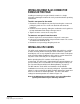
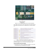
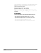
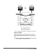
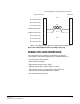
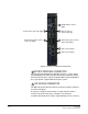
Table Of Contents
- The Eclipse Omega Matrix System: An Overview
- Operation
- The Eclipse Omega Matrix and Circuit Cards
- Front-Panel Controls and Lights
- Central Processor Unit (CPU) Card Description
- Analog Port Card Description
- Power Supply Description
- Connecting the Matrix
- Eclipse Fiber Linking
- Eclipse E-QUE Interface
- Eclipse IVC-32 Interface
- Eclipse LMC-64 Interface
- Installation
- Reconnecting the CPU Card’s Backup Battery
- Verifying the Shipment
- Unpacking the System
- Installing the Eclipse Omega Matrix
- Installing Power Supplies
- Installing the Rear RJ-45 Connector Panels
- Installing Rear RJ-45 Connector Panels in the Field
- Installing CPU Cards
- Installing Analog Port and Expansion Cards
- Wiring Audio Devices to the Matrix
- Wiring CPU Card Interfaces
- GPI/RLY Interface Connector
- RS-232 DB-9 Connector
- Alarm I/O Connector
- General-Purpose Outputs Connector (GP OUT)
- General-Purpose Inputs Connector (GP IN)
- Local Area Network Connectors (LAN1 and LAN2)
- E1/T1 Matrix to Matrix Crossover Cable
- E1/T1 Straight Cable Connections
- E1 to FreeSpeak/CellCom Antenna Pinout
- Maintenance
- Specifications
- Glossary
- Limited Warranty
- Technical Support & Repair Policy
Clear-Com
Eclipse Omega Instruction Manual
7-12
Figure 7-4: Wiring from the Matrix to an Analog Panel Using RJ-45
Single-Pair Digital
Single-pair digital wiring is accomplished with double-shielded 24
AWG conductor CAT-6E enhanced STP cable. Pair 1 transmits and
receives multiplexed digital and analog between the matrix and the
panel.
Note: Ensure that the “select” switch on the rear of the panel is in
the correct position for the intended use.
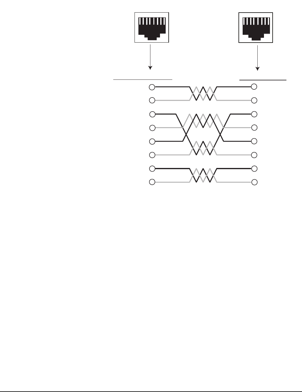
RJ-45 CONNECTOR
AT MATRIX PORT
RJ-45 CONNECTOR ON
PANEL OR INTERFACE
Matrix Frame RJ-45 Pin Numbers
Shielded category-5 cables wired pin-to-pin
Panel RJ-45 Pin Numbers
Pair 2
Pair 1
Pair 3
Pair 4
RS-422 Input +
(into Matrix)
RS-422 Input –
(into Matrix)
Audio Input +
(into Matrix)
Audio Output +
(from Matrix)
Audio Output –
(from Matrix)
Audio Input –
(into Matrix)
RS-422 Output +
(from Matrix)
RS-422 Output –
(from Matrix)
1
2
3
5
6
7
1
2
6
7
8
4
3
4
5
8
RS-422 Output +
(from panel)
RS-422 Output –
(from panel)
Audio Output +
(from panel)
Audio Input +
(into panel)
Audio Input –
(into panel)
Audio Output –
(from panel)
RS-422 Input +
(into panel)
RS-422 Input –
(into panel)
Pair 1 Audio output from Matrix to panel
Pair 2 RS-422 data input from panel to Matrix
Pair 3 Audio input from panel to Matrix
Pair 4 RS-422 data output from Matrix to panel
8
7
65
4
3
2
1
8
7
6
5
4
3
2
1
Views from
front of
connectors