
Instruction Manual
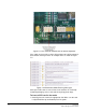
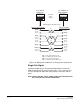
Table Of Contents
- The Eclipse Omega Matrix System: An Overview
- Operation
- The Eclipse Omega Matrix and Circuit Cards
- Front-Panel Controls and Lights
- Central Processor Unit (CPU) Card Description
- Analog Port Card Description
- Power Supply Description
- Connecting the Matrix
- Eclipse Fiber Linking
- Eclipse E-QUE Interface
- Eclipse IVC-32 Interface
- Eclipse LMC-64 Interface
- Installation
- Reconnecting the CPU Card’s Backup Battery
- Verifying the Shipment
- Unpacking the System
- Installing the Eclipse Omega Matrix
- Installing Power Supplies
- Installing the Rear RJ-45 Connector Panels
- Installing Rear RJ-45 Connector Panels in the Field
- Installing CPU Cards
- Installing Analog Port and Expansion Cards
- Wiring Audio Devices to the Matrix
- Wiring CPU Card Interfaces
- GPI/RLY Interface Connector
- RS-232 DB-9 Connector
- Alarm I/O Connector
- General-Purpose Outputs Connector (GP OUT)
- General-Purpose Inputs Connector (GP IN)
- Local Area Network Connectors (LAN1 and LAN2)
- E1/T1 Matrix to Matrix Crossover Cable
- E1/T1 Straight Cable Connections
- E1 to FreeSpeak/CellCom Antenna Pinout
- Maintenance
- Specifications
- Glossary
- Limited Warranty
- Technical Support & Repair Policy

Clear-Com
Eclipse Omega Instruction Manual
7-11
supply combinations. If each AC input is connected to a different mains
AC branch, one power supply will continue to operate if the other
supply’s mains AC branch opens.
WIRING PANELS TO THE MATRIX
Eclipse uses a 4-pair (analog) or single-pair (digital) wiring scheme
between the matrix and panels. All Eclipse panels have built-in RJ-45
connectors.
4-Pair Analog
Four-pair analog wiring is done with shielded CAT5 RJ-45 cable.
• Pair 1 transmits analog audio from the matrix to the panel.
• Pair 2 transmits digital data from the panel back to the matrix.
• Pair 3 transmits audio from the panel to the matrix.
• Pair 4 transmits digital data from the matrix back to the panel.