
Instruction Manual
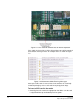
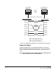
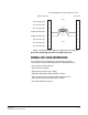
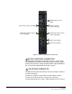
Table Of Contents
- The Eclipse Omega Matrix System: An Overview
- Operation
- The Eclipse Omega Matrix and Circuit Cards
- Front-Panel Controls and Lights
- Central Processor Unit (CPU) Card Description
- Analog Port Card Description
- Power Supply Description
- Connecting the Matrix
- Eclipse Fiber Linking
- Eclipse E-QUE Interface
- Eclipse IVC-32 Interface
- Eclipse LMC-64 Interface
- Installation
- Reconnecting the CPU Card’s Backup Battery
- Verifying the Shipment
- Unpacking the System
- Installing the Eclipse Omega Matrix
- Installing Power Supplies
- Installing the Rear RJ-45 Connector Panels
- Installing Rear RJ-45 Connector Panels in the Field
- Installing CPU Cards
- Installing Analog Port and Expansion Cards
- Wiring Audio Devices to the Matrix
- Wiring CPU Card Interfaces
- GPI/RLY Interface Connector
- RS-232 DB-9 Connector
- Alarm I/O Connector
- General-Purpose Outputs Connector (GP OUT)
- General-Purpose Inputs Connector (GP IN)
- Local Area Network Connectors (LAN1 and LAN2)
- E1/T1 Matrix to Matrix Crossover Cable
- E1/T1 Straight Cable Connections
- E1 to FreeSpeak/CellCom Antenna Pinout
- Maintenance
- Specifications
- Glossary
- Limited Warranty
- Technical Support & Repair Policy

Clear-Com
Eclipse Omega Instruction Manual
7-10
Communication to a card’s connected devices will be interrupted when
that card is removed from the matrix. When the card is replaced,
communication is restored.
SLOT NUMBERING
Each MVX-A16 interface has circuitry to support 16 analog ports. A
grid printed on the matrix’s rear panel gives the numbering scheme for
the analog ports.
CONFIGURATION
When an interface is physically installed, its ports must be assigned
functions from the Eclipse Configuration Software (ECS). Refer to the
Eclipse Configuration Software Instruction Manual (part 810299Z) for
more information.
VERIFYING ANALOG PORT CARD INSTALLATION
The operating status of the matrix can be checked by viewing the
front-panel status lights. The following lights indicate that an analog
port card has been properly installed in the matrix:
• When lit, the four power-supply lights indicate that the associated
power supplies are operating properly. The four lights are +12V, -12V,
+5V, and +3.3V.
• The column of 16 yellow lights labeled “active” corresponds to the
card’s 16 ports. When lit, an “active” light indicates that there is a
device connected to that port and that communication is running
properly between the card and the device.
• The column of 16 green lights labeled “VOX” corresponds to the
card’s 16 ports. When lit, a “VOX” light indicates the audio level on
that port’s connected audio device has exceeded a threshold. The
threshold audio level is set for that port’s connected audio device in
the ECS configuration software.
• The green “frame data” light illuminates green when information has
successfully passed between the CPU card and the analog port card.
• The red “status” light illuminates when the analog port card fails to
communicate with the CPU card.
WIRING AUDIO DEVICES TO THE MATRIX
The Eclipse Matrix Installation Manual (part 810298Z) gives complete
details about wiring audio devices to the matrix. The installation
manual also discusses RJ-45 cables and other types of cable required
for system installation.
The Eclipse Omega system features two IEC mains AC power
connectors that provide separate power inputs for redundant power