
Instruction Manual
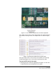
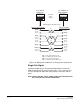
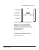
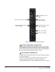
Table Of Contents
- The Eclipse Omega Matrix System: An Overview
- Operation
- The Eclipse Omega Matrix and Circuit Cards
- Front-Panel Controls and Lights
- Central Processor Unit (CPU) Card Description
- Analog Port Card Description
- Power Supply Description
- Connecting the Matrix
- Eclipse Fiber Linking
- Eclipse E-QUE Interface
- Eclipse IVC-32 Interface
- Eclipse LMC-64 Interface
- Installation
- Reconnecting the CPU Card’s Backup Battery
- Verifying the Shipment
- Unpacking the System
- Installing the Eclipse Omega Matrix
- Installing Power Supplies
- Installing the Rear RJ-45 Connector Panels
- Installing Rear RJ-45 Connector Panels in the Field
- Installing CPU Cards
- Installing Analog Port and Expansion Cards
- Wiring Audio Devices to the Matrix
- Wiring CPU Card Interfaces
- GPI/RLY Interface Connector
- RS-232 DB-9 Connector
- Alarm I/O Connector
- General-Purpose Outputs Connector (GP OUT)
- General-Purpose Inputs Connector (GP IN)
- Local Area Network Connectors (LAN1 and LAN2)
- E1/T1 Matrix to Matrix Crossover Cable
- E1/T1 Straight Cable Connections
- E1 to FreeSpeak/CellCom Antenna Pinout
- Maintenance
- Specifications
- Glossary
- Limited Warranty
- Technical Support & Repair Policy

Clear-Com
Eclipse Omega Instruction Manual
7-8
INSTALLING ANALOG PORT AND EXPAN-
SION CARDS
Before installing an analog port or expansion card, the card’s
associated rear-connector panel should be installed.
The order in which the cards are installed from left to right must be
considered before installation in order to ensure that the system will
function correctly.
The order (left to right) in which the cards must be installed is:
• First: MVX-A16 cards (normally in leftmost slots)
• Second: IVC-32 cards
• Third: LMC-64 cards
• Fourth: E-Que Antenna cards
• Fifth: E-Que Splitter cards
• Sixth: E-Que Trunk cards
• Seventh: E-Fib cards (normally in the rightmost slots)
The Eclipse system has a limit of 240 audio ports which may be
allocated to MVX-A16 cards or IVC-32 cards. Each MVX-A16 card
uses 16 audio ports and each IVC-32 card uses 32 audio ports from
the total. The total of 240 audio ports can be made up of any
combination of MVX-A16 and IVC-32 cards; any audio ports beyond
the 240 limit will not be recognised by the system.
For example an Omega matrix system could contain a maximum of 15
MVX-A16 cards which would fill the frame and use the maximum
number of audio ports supported:
15 MVX cards * 16 ports = 240
Up to 4 IVC-32 cards could be installed, using 128 audio ports. This
would allow a further 7 MVX-A16 cards to be added:
(4 IVC-32 cards * 32 ports) + (7 MVX cards * 16 ports) = 240
If 8 MVX cards were installed this would take the port count to 256
resulting in an invalid system configuration.
LMC-64 cards normally use a different port allocation and do not use
any of the audio port allocation. LMC-64 cards are configured in ECS
to 16, 32, 48 or 64 audio meters and the same numbers of ports are
allocated at that time. When an audio level meter is configured using
Production Maestro Pro one of the ports allocated to the LMC-64 card
is used. If the same audio level meter is being used by more than one
Production Maestro Pro client this does not increase the port usage as
the audio level data is broadcast.