
Instruction Manual
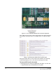
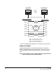
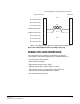
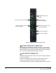
Table Of Contents
- The Eclipse Omega Matrix System: An Overview
- Operation
- The Eclipse Omega Matrix and Circuit Cards
- Front-Panel Controls and Lights
- Central Processor Unit (CPU) Card Description
- Analog Port Card Description
- Power Supply Description
- Connecting the Matrix
- Eclipse Fiber Linking
- Eclipse E-QUE Interface
- Eclipse IVC-32 Interface
- Eclipse LMC-64 Interface
- Installation
- Reconnecting the CPU Card’s Backup Battery
- Verifying the Shipment
- Unpacking the System
- Installing the Eclipse Omega Matrix
- Installing Power Supplies
- Installing the Rear RJ-45 Connector Panels
- Installing Rear RJ-45 Connector Panels in the Field
- Installing CPU Cards
- Installing Analog Port and Expansion Cards
- Wiring Audio Devices to the Matrix
- Wiring CPU Card Interfaces
- GPI/RLY Interface Connector
- RS-232 DB-9 Connector
- Alarm I/O Connector
- General-Purpose Outputs Connector (GP OUT)
- General-Purpose Inputs Connector (GP IN)
- Local Area Network Connectors (LAN1 and LAN2)
- E1/T1 Matrix to Matrix Crossover Cable
- E1/T1 Straight Cable Connections
- E1 to FreeSpeak/CellCom Antenna Pinout
- Maintenance
- Specifications
- Glossary
- Limited Warranty
- Technical Support & Repair Policy

Clear-Com
Eclipse Omega Instruction Manual
7-7
2. When the card has almost reached the backplane connectors, open
the two ejectors, allowing them to clear the edges of the matrix.
Gently insert the card further until it touches the backplane
connector guides.
3. Gently close both ejector tabs at the same time, which will propel the
card into the backplane connectors.
To remove a CPU card from the matrix
1. Two card ejector tabs, located at the top and bottom of the CPU
card, hold the card in place in the matrix. To remove a card, open
the two ejector tabs at the same time until the card unseats from its
backplane connectors.
2. Pull the card out of the matrix.
HOT PATCHING
The CPU cards are “hot patchable” and “self initializing”. When the
matrix is fitted with two CPU cards, a faulty CPU card can be removed
and replaced while the system is powered because the second CPU
card will automatically begin operating when the first card is removed.
Sometimes, re-inserting a CPU can reset the matrix. It is advisable to
replace CPUs in maintenance down times.
VERIFYING THE CPU CARD INSTALLATION
The CPU card’s operating status can be checked by looking at the
lights on the front of the card. The following lights indicate that the card
has been properly installed in the matrix:
• The two power-supply lights, labeled “+5V” and “+3.3V”, illuminate
green steadily to indicate that the power supplies are present.
• The dot-matrix array of lights displays a number to indicate which of
the four stored configurations in the card’s memory is currently
operating.
• The “OK” light flashes to indicate that the CPU card software is
running.
• The “master” light illuminates steadily on the currently active CPU
card, indicating that the CPU card is properly installed and operating
correctly.