
Instruction Manual
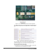
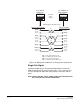
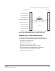
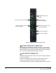
Table Of Contents
- The Eclipse Omega Matrix System: An Overview
- Operation
- The Eclipse Omega Matrix and Circuit Cards
- Front-Panel Controls and Lights
- Central Processor Unit (CPU) Card Description
- Analog Port Card Description
- Power Supply Description
- Connecting the Matrix
- Eclipse Fiber Linking
- Eclipse E-QUE Interface
- Eclipse IVC-32 Interface
- Eclipse LMC-64 Interface
- Installation
- Reconnecting the CPU Card’s Backup Battery
- Verifying the Shipment
- Unpacking the System
- Installing the Eclipse Omega Matrix
- Installing Power Supplies
- Installing the Rear RJ-45 Connector Panels
- Installing Rear RJ-45 Connector Panels in the Field
- Installing CPU Cards
- Installing Analog Port and Expansion Cards
- Wiring Audio Devices to the Matrix
- Wiring CPU Card Interfaces
- GPI/RLY Interface Connector
- RS-232 DB-9 Connector
- Alarm I/O Connector
- General-Purpose Outputs Connector (GP OUT)
- General-Purpose Inputs Connector (GP IN)
- Local Area Network Connectors (LAN1 and LAN2)
- E1/T1 Matrix to Matrix Crossover Cable
- E1/T1 Straight Cable Connections
- E1 to FreeSpeak/CellCom Antenna Pinout
- Maintenance
- Specifications
- Glossary
- Limited Warranty
- Technical Support & Repair Policy

Clear-Com
Eclipse Omega Instruction Manual
7-5
INSTALLING REAR RJ-45 CONNECTOR
PANELS IN THE FIELD
Installing or removing a rear panel from the matrix is a simple
procedure, allowing the matrix to be easily customized to the operating
environment.
To add a rear panel to the matrix
1. Remove the desired blank rear panel by loosening the screws and
pulling the panel out. The screws are attached and cannot be
removed.
2. Install the new rear panel by sliding the card into the card’s guides at
the top and bottom of the Eclipse Omega chassis.
3. Tighten all of the screws on the rear panel.
To remove a rear panel from the matrix
1. Detach any devices connected to the rear panel’s connectors.
2. Loosen the screws that hold the rear panel to the matrix. The screws
are attached and will not fall off.
3. Remove the rear panel by pulling the panel out.
INSTALLING CPU CARDS
The CPU card’s components include CMOS chips which are sensitive
to static electricity. Before touching the CPU card touch a grounded
metal object, such as any unpainted surface on the matrix, to dissipate
static electricity. While handling the CPU card, be careful not to bend
any of the card’s connector pins or component leads.
Before operating the CPU card the card’s battery must be
reconnected. The CPU card is shipped with a disconnected battery to
preserve battery life. For instructions on reconnecting the battery, see
See “Reconnecting the CPU Card’s Backup Battery” on page 7-1.
The DIP switches on the CPU card should be checked before
installation to ensure they are correctly configured. In particular SW3
switch 2 is only used to put the MVX card into maintenance mode and
must be set to OFF for normal operation. The CPU card switch
settings for normal operation are shown in Figure 7-2.
Note: If the Maintenance mode switch is set to the ON position
system performance may be adversely affected.