
Instruction Manual

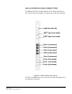
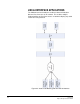
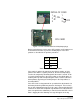


Table Of Contents
- The Eclipse Omega Matrix System: An Overview
- Operation
- The Eclipse Omega Matrix and Circuit Cards
- Front-Panel Controls and Lights
- Central Processor Unit (CPU) Card Description
- Analog Port Card Description
- Power Supply Description
- Connecting the Matrix
- Eclipse Fiber Linking
- Eclipse E-QUE Interface
- Eclipse IVC-32 Interface
- Eclipse LMC-64 Interface
- Installation
- Reconnecting the CPU Card’s Backup Battery
- Verifying the Shipment
- Unpacking the System
- Installing the Eclipse Omega Matrix
- Installing Power Supplies
- Installing the Rear RJ-45 Connector Panels
- Installing Rear RJ-45 Connector Panels in the Field
- Installing CPU Cards
- Installing Analog Port and Expansion Cards
- Wiring Audio Devices to the Matrix
- Wiring CPU Card Interfaces
- GPI/RLY Interface Connector
- RS-232 DB-9 Connector
- Alarm I/O Connector
- General-Purpose Outputs Connector (GP OUT)
- General-Purpose Inputs Connector (GP IN)
- Local Area Network Connectors (LAN1 and LAN2)
- E1/T1 Matrix to Matrix Crossover Cable
- E1/T1 Straight Cable Connections
- E1 to FreeSpeak/CellCom Antenna Pinout
- Maintenance
- Specifications
- Glossary
- Limited Warranty
- Technical Support & Repair Policy

Clear-Com
Eclipse Omega Instruction Manual
7-4
INSTALLING THE ECLIPSE OMEGA MATRIX
The following overview gives a summary of the steps required to install
an Eclipse Omega matrix. More detailed information on each step is
provided in the sections that follow.
To install an Eclipse Omega matrix
1. Remove the Eclipse Omega matrix chassis from its shipping carton.
2. Leave at least 2 inches (51 mm) of clearance on all sides of the
matrix chassis to ensure proper airflow. Do not block ventilation
vents.
3. Check the position of circuit cards, power supplies, and
rear-connector panels. Later sections in this chapter give more
information on these items.
4. Apply AC power to the unit. The unit has two separate AC power
entry connectors for the two separate power supplies in the system.
INSTALLING POWER SUPPLIES
The Eclipse Omega system’s DC power supplies run on AC mains
power. Two identical Euro Cassette power supplies are provided to
ensure that every matrix will have redundant power—that is, to ensure
that the matrix will continue to operate even if one supply output fails.
Each of the power supplies must be connected to a dedicated branch
of AC mains power. The matrix will continue to operate even if one of
the AC power branches fails.
Clear-Com ships each matrix with power supplies already installed.
When the matrix is installed connect the power supplies to AC mains
power using the IEC power connectors on the matrix’s rear panel.
A fully equipped Eclipse Omega matrix (13 port cards, 2 expansion
cards) requires 100 to 240 VAC at 40 to 50 Hz with a maximum
dissipation of 300W.
INSTALLING THE REAR RJ-45 CONNECTOR
PANELS
The matrix’s rear panel is constructed of modular,
individually-installable connector panels. Each port or expansion card
has a corresponding rear-connector panel. Each MVX-A16 rear
connector panel holds 16 RJ-45 connectors. E-FIB rear cards contain
two fiber connectors and E-QUE, IVC-32 and LMC-64 rear cards
contain 11 RJ-45 connectors.
Clear-Com ships each matrix with the required number of
rear-connector panels already installed. Blank rear panels fill unused
card slots.