
Instruction Manual
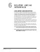
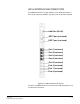
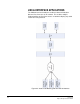
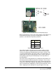
Table Of Contents
- The Eclipse Omega Matrix System: An Overview
- Operation
- The Eclipse Omega Matrix and Circuit Cards
- Front-Panel Controls and Lights
- Central Processor Unit (CPU) Card Description
- Analog Port Card Description
- Power Supply Description
- Connecting the Matrix
- Eclipse Fiber Linking
- Eclipse E-QUE Interface
- Eclipse IVC-32 Interface
- Eclipse LMC-64 Interface
- Installation
- Reconnecting the CPU Card’s Backup Battery
- Verifying the Shipment
- Unpacking the System
- Installing the Eclipse Omega Matrix
- Installing Power Supplies
- Installing the Rear RJ-45 Connector Panels
- Installing Rear RJ-45 Connector Panels in the Field
- Installing CPU Cards
- Installing Analog Port and Expansion Cards
- Wiring Audio Devices to the Matrix
- Wiring CPU Card Interfaces
- GPI/RLY Interface Connector
- RS-232 DB-9 Connector
- Alarm I/O Connector
- General-Purpose Outputs Connector (GP OUT)
- General-Purpose Inputs Connector (GP IN)
- Local Area Network Connectors (LAN1 and LAN2)
- E1/T1 Matrix to Matrix Crossover Cable
- E1/T1 Straight Cable Connections
- E1 to FreeSpeak/CellCom Antenna Pinout
- Maintenance
- Specifications
- Glossary
- Limited Warranty
- Technical Support & Repair Policy
Clear-Com
Eclipse Omega Instruction Manual
7-2
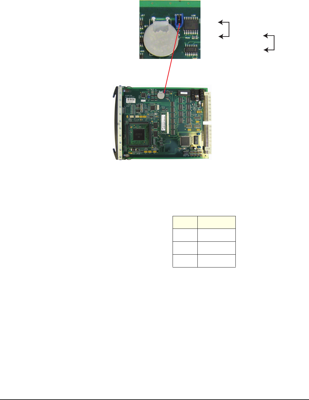
Figure 7-1: CPU card with detail of CON9 jumper plugs
Before performing any service on the CPU card the card’s battery must
be disconnected. To do so, place the CON9 jumpers in the OFF
position as described in the previous procedure.
Table 7-1: CON9 Pin Configuration
If the matrix is going to be stored for more than 3 months, or if the
power to the matrix is regularly turned off, the CPU backup battery
needs to be temporarily deactivated while the matrix is stored. To do
so, put the CON9 jumper in the OFF position as described above. In
order to power up and start operating the matrix, reconnect the CPU
backup battery by placing the CON9 jumper in the ON position, as
described above.
If the CPU card is left unpowered for a period of time the batteries for
the battery backed up RAM may become discharged. This results in
the run time information being lost. If this state is detected by the CPU
card then the CPU card will provide signalization on its OK LED in the
form of 2 rapid flashes followed by a slow flash of the OK LED. Also if
ECS is logging then the following message will appear in the log.
PIN STATUS
1On
2Common
3Off
CPU CARD
DETAIL OF CON9
1
2
3
ON
1
2
3
OFF