
Instruction Manual
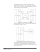

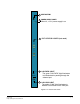
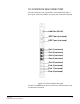
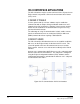
Table Of Contents
- The Eclipse Omega Matrix System: An Overview
- Operation
- The Eclipse Omega Matrix and Circuit Cards
- Front-Panel Controls and Lights
- Central Processor Unit (CPU) Card Description
- Analog Port Card Description
- Power Supply Description
- Connecting the Matrix
- Eclipse Fiber Linking
- Eclipse E-QUE Interface
- Eclipse IVC-32 Interface
- Eclipse LMC-64 Interface
- Installation
- Reconnecting the CPU Card’s Backup Battery
- Verifying the Shipment
- Unpacking the System
- Installing the Eclipse Omega Matrix
- Installing Power Supplies
- Installing the Rear RJ-45 Connector Panels
- Installing Rear RJ-45 Connector Panels in the Field
- Installing CPU Cards
- Installing Analog Port and Expansion Cards
- Wiring Audio Devices to the Matrix
- Wiring CPU Card Interfaces
- GPI/RLY Interface Connector
- RS-232 DB-9 Connector
- Alarm I/O Connector
- General-Purpose Outputs Connector (GP OUT)
- General-Purpose Inputs Connector (GP IN)
- Local Area Network Connectors (LAN1 and LAN2)
- E1/T1 Matrix to Matrix Crossover Cable
- E1/T1 Straight Cable Connections
- E1 to FreeSpeak/CellCom Antenna Pinout
- Maintenance
- Specifications
- Glossary
- Limited Warranty
- Technical Support & Repair Policy
Clear-Com
Eclipse Omega Instruction Manual
5-5
IVC-32 INTERFACE REAR CONNECTIONS
The IVC-32 interface rear card contains eleven RJ45 connectors; 8
E1/T1 ports (not used), 2 DECT sync ports (not used) and a LAN port.
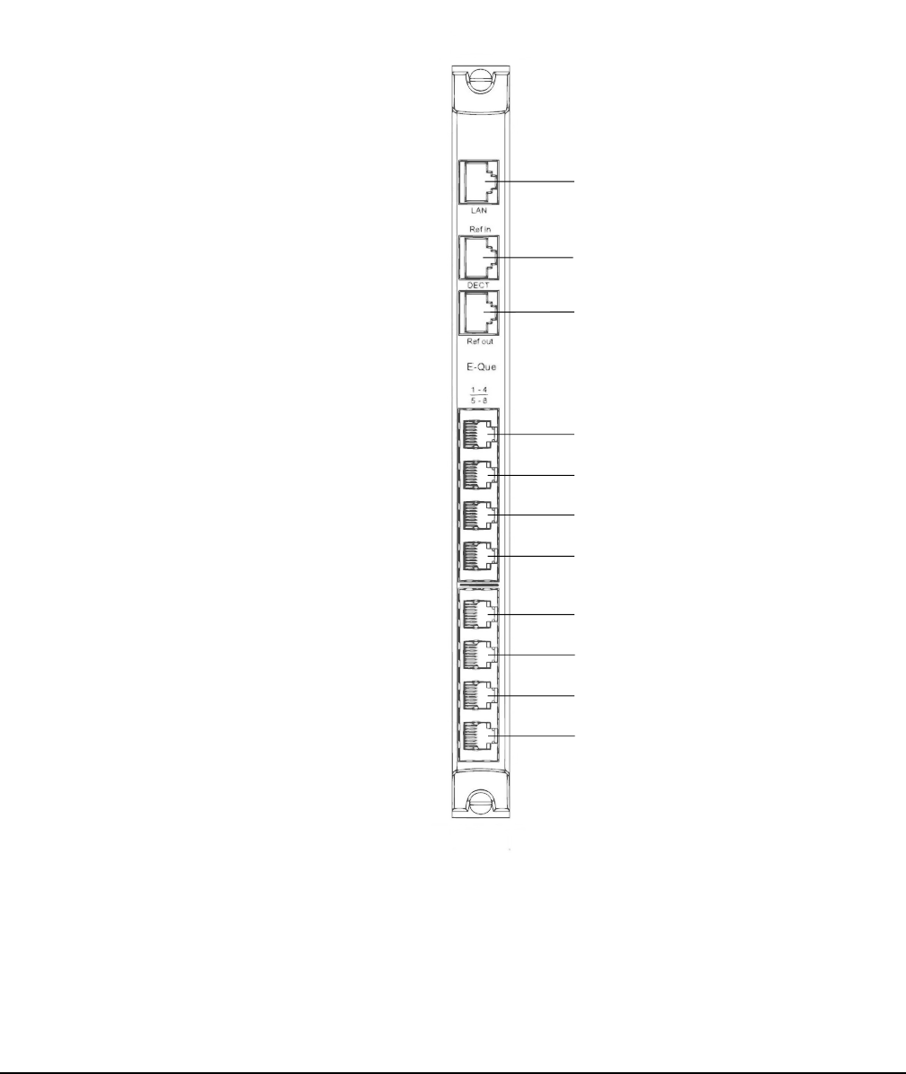
Figure 5-2: IVC-32 Interface Rear Card
The E1/T1 and DECT ports are not used on the IVC-32 interface and
should not be connected.
LAN Port (RJ-45)
DECT port (not used)
DECT port (not used)
Port 1 (not used)
Port 2 (not used)
Port 3 (not used)
Port 4 (not used)
Port 5 (not used)
Port 6 (not used)
Port 7 (not used)
Port 8 (not used)