
Instruction Manual
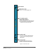
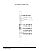
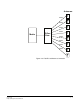
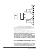
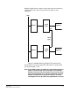
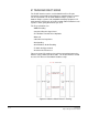
Table Of Contents
- The Eclipse Omega Matrix System: An Overview
- Operation
- The Eclipse Omega Matrix and Circuit Cards
- Front-Panel Controls and Lights
- Central Processor Unit (CPU) Card Description
- Analog Port Card Description
- Power Supply Description
- Connecting the Matrix
- Eclipse Fiber Linking
- Eclipse E-QUE Interface
- Eclipse IVC-32 Interface
- Eclipse LMC-64 Interface
- Installation
- Reconnecting the CPU Card’s Backup Battery
- Verifying the Shipment
- Unpacking the System
- Installing the Eclipse Omega Matrix
- Installing Power Supplies
- Installing the Rear RJ-45 Connector Panels
- Installing Rear RJ-45 Connector Panels in the Field
- Installing CPU Cards
- Installing Analog Port and Expansion Cards
- Wiring Audio Devices to the Matrix
- Wiring CPU Card Interfaces
- GPI/RLY Interface Connector
- RS-232 DB-9 Connector
- Alarm I/O Connector
- General-Purpose Outputs Connector (GP OUT)
- General-Purpose Inputs Connector (GP IN)
- Local Area Network Connectors (LAN1 and LAN2)
- E1/T1 Matrix to Matrix Crossover Cable
- E1/T1 Straight Cable Connections
- E1 to FreeSpeak/CellCom Antenna Pinout
- Maintenance
- Specifications
- Glossary
- Limited Warranty
- Technical Support & Repair Policy
Clear-Com
Eclipse Omega Instruction Manual
4-9
Multiple E-QUE interfaces within a single matrix do not need to have
external DECT sync cables connected as the signal uses the
backplane.
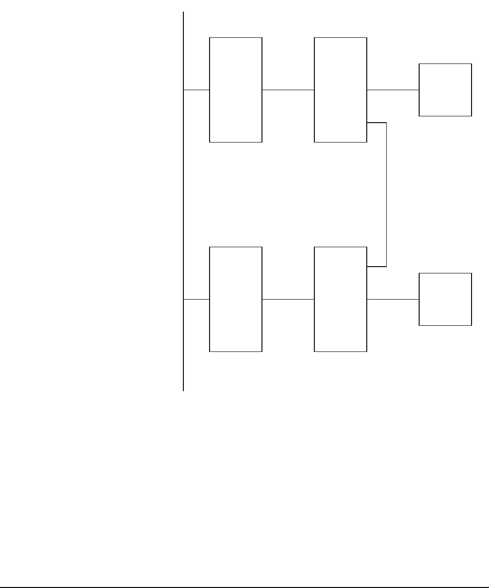
Figure 4-5: Multiple Matrices with DECT Sync Interconnect
All connections are made using CAT5 cable and it is recommended
that shielded cable is used.
Note: If an E-QUE interface is fitted in the matrix with antennae or
splitters connected and active inserting a second E-QUE
interface to the left of the first interface (seen from the front)
will cause a temporary loss of audio to beltpacks using the
original E-QUE interface (usually for about 10 seconds).
The beltpacks do not go offline and signalization is not lost.
Matrix 1
Matrix 2
E-Que
Card 1
E-Que
Card 2
Splitter 1
Splitter 2
DECT
Sync
LAN
Out
In