
Instruction Manual

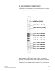
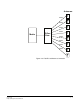
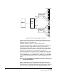
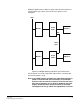
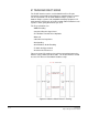
Table Of Contents
- The Eclipse Omega Matrix System: An Overview
- Operation
- The Eclipse Omega Matrix and Circuit Cards
- Front-Panel Controls and Lights
- Central Processor Unit (CPU) Card Description
- Analog Port Card Description
- Power Supply Description
- Connecting the Matrix
- Eclipse Fiber Linking
- Eclipse E-QUE Interface
- Eclipse IVC-32 Interface
- Eclipse LMC-64 Interface
- Installation
- Reconnecting the CPU Card’s Backup Battery
- Verifying the Shipment
- Unpacking the System
- Installing the Eclipse Omega Matrix
- Installing Power Supplies
- Installing the Rear RJ-45 Connector Panels
- Installing Rear RJ-45 Connector Panels in the Field
- Installing CPU Cards
- Installing Analog Port and Expansion Cards
- Wiring Audio Devices to the Matrix
- Wiring CPU Card Interfaces
- GPI/RLY Interface Connector
- RS-232 DB-9 Connector
- Alarm I/O Connector
- General-Purpose Outputs Connector (GP OUT)
- General-Purpose Inputs Connector (GP IN)
- Local Area Network Connectors (LAN1 and LAN2)
- E1/T1 Matrix to Matrix Crossover Cable
- E1/T1 Straight Cable Connections
- E1 to FreeSpeak/CellCom Antenna Pinout
- Maintenance
- Specifications
- Glossary
- Limited Warranty
- Technical Support & Repair Policy
Clear-Com
Eclipse Omega Instruction Manual
4-5
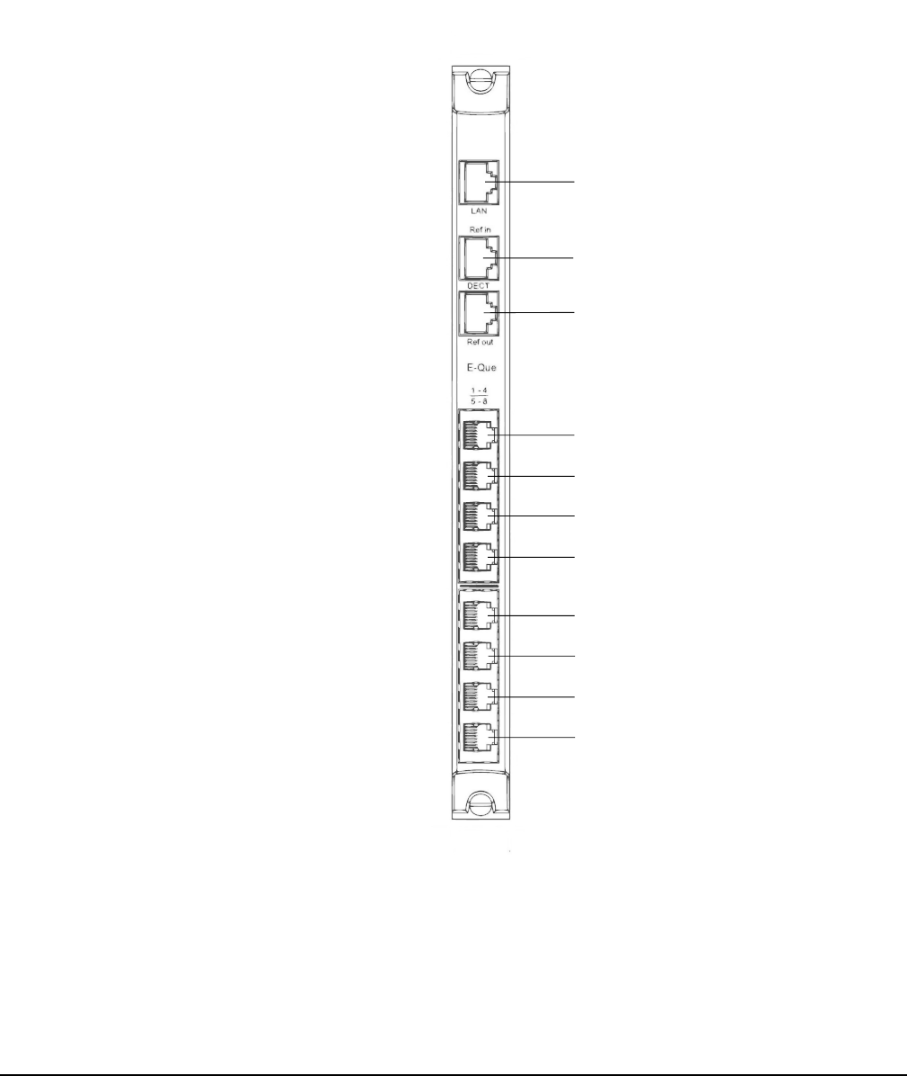
E-QUE CARD REAR CONNECTIONS
The E-QUE rear card contains eleven RJ45 connectors; 8 E1/T1 ports,
2 DECT sync ports and a LAN port.
Figure 4-2: E-QUE Card Rear
When multiple E-QUE cards are fitted in a rack, one of the cards
generates a clock signal, which all other cards lock to, to ensure that
all antennas remain in sync. The system is designed such that the
leftmost card (seen from the front) is always the one which generates
LAN Port (RJ-45)
DECT Ref in (RJ-45)
DECT Ref out (RJ-45)
E1/T1 Port 1 (RJ-45)
E1/T1 Port 2 (RJ-45)
E1/T1 Port 3 (RJ-45)
E1/T1 Port 4 (RJ-45)
E1 /T1 Port 5 (RJ-45)
E1/T1 Port 6 (RJ-45)
E1/T1 Port 7 (RJ-45)
E1/T1 Port 8 (RJ-45)