
Instruction Manual
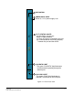
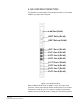
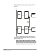
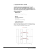
Table Of Contents
- The Eclipse Omega Matrix System: An Overview
- Operation
- The Eclipse Omega Matrix and Circuit Cards
- Front-Panel Controls and Lights
- Central Processor Unit (CPU) Card Description
- Analog Port Card Description
- Power Supply Description
- Connecting the Matrix
- Eclipse Fiber Linking
- Eclipse E-QUE Interface
- Eclipse IVC-32 Interface
- Eclipse LMC-64 Interface
- Installation
- Reconnecting the CPU Card’s Backup Battery
- Verifying the Shipment
- Unpacking the System
- Installing the Eclipse Omega Matrix
- Installing Power Supplies
- Installing the Rear RJ-45 Connector Panels
- Installing Rear RJ-45 Connector Panels in the Field
- Installing CPU Cards
- Installing Analog Port and Expansion Cards
- Wiring Audio Devices to the Matrix
- Wiring CPU Card Interfaces
- GPI/RLY Interface Connector
- RS-232 DB-9 Connector
- Alarm I/O Connector
- General-Purpose Outputs Connector (GP OUT)
- General-Purpose Inputs Connector (GP IN)
- Local Area Network Connectors (LAN1 and LAN2)
- E1/T1 Matrix to Matrix Crossover Cable
- E1/T1 Straight Cable Connections
- E1 to FreeSpeak/CellCom Antenna Pinout
- Maintenance
- Specifications
- Glossary
- Limited Warranty
- Technical Support & Repair Policy
Clear-Com
Eclipse Omega Instruction Manual
4-3
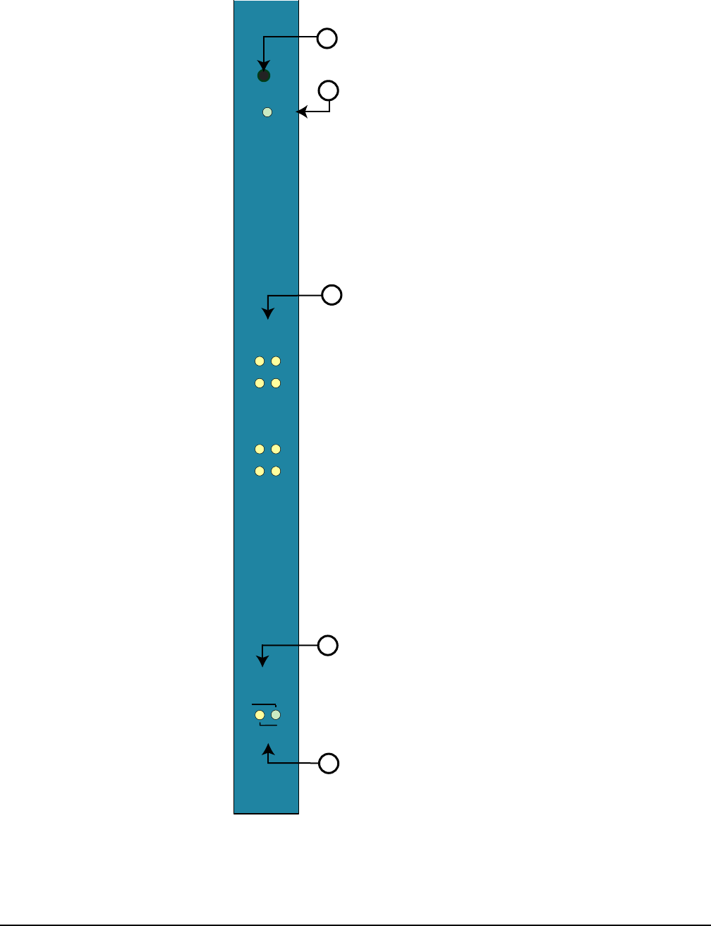
Figure 4-1: Front E-Que Card
+3.3V
STATUS
1
2
3
4
5
6
7
8
RESET
POWER SUPPLY LIGHTS
E1/T1 STATUS LIGHTS
LAN DATA LIGHT
The green "LAN DATA" light illuminates
to indicate data is passing through the
ethernet port
LAN LINK LIGHT
The amber "LINK" light illuminates to
indicate a connection on the LAN port.
When lit, +3.3 V power supply is on
8 yellow lights, one per port
When on, light indicates:
(1) There is a device connected to the port.
(2) Communications are running properly
between the port and the device.
RESET BUTTON
1
2
3
LAN
DATA
LINK
4
5