
Instruction Manual


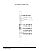
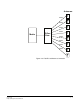
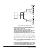
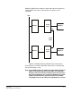
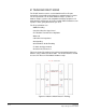
Table Of Contents
- The Eclipse Omega Matrix System: An Overview
- Operation
- The Eclipse Omega Matrix and Circuit Cards
- Front-Panel Controls and Lights
- Central Processor Unit (CPU) Card Description
- Analog Port Card Description
- Power Supply Description
- Connecting the Matrix
- Eclipse Fiber Linking
- Eclipse E-QUE Interface
- Eclipse IVC-32 Interface
- Eclipse LMC-64 Interface
- Installation
- Reconnecting the CPU Card’s Backup Battery
- Verifying the Shipment
- Unpacking the System
- Installing the Eclipse Omega Matrix
- Installing Power Supplies
- Installing the Rear RJ-45 Connector Panels
- Installing Rear RJ-45 Connector Panels in the Field
- Installing CPU Cards
- Installing Analog Port and Expansion Cards
- Wiring Audio Devices to the Matrix
- Wiring CPU Card Interfaces
- GPI/RLY Interface Connector
- RS-232 DB-9 Connector
- Alarm I/O Connector
- General-Purpose Outputs Connector (GP OUT)
- General-Purpose Inputs Connector (GP IN)
- Local Area Network Connectors (LAN1 and LAN2)
- E1/T1 Matrix to Matrix Crossover Cable
- E1/T1 Straight Cable Connections
- E1 to FreeSpeak/CellCom Antenna Pinout
- Maintenance
- Specifications
- Glossary
- Limited Warranty
- Technical Support & Repair Policy

Clear-Com
Eclipse Omega Instruction Manual
4-1
ECLIPSE E-QUE
INTERFACE
E-QUE INTERFACE DESCRIPTION
The E-QUE interface allows the Eclipse matrix connectivity to
FreeSpeak/CellCom antennas and FreeSpeak/CellCom antenna
splitters, E1 and T1 trunk lines and E1 direct lines. The E-QUE
interfaces must be fitted in the rightmost available slots on the Omega
(furthest from the config cards) and up to four E-QUE interfaces can be
fitted on an Eclipse Omega matrix.
The FreeSpeak/CellCom connection options supported are:
• Up to 8 x FreeSpeak/CellCom antenna direct connections per
E-QUE interface.
• Up to 2 x FreeSpeak/CellCom splitter connections (up to 5
antennas each) per E-QUE interface.
Using all four E-QUE interfaces that can be fitted would allow up to 40
antennas and 200 beltpacks can be connected to a matrix.
The E-QUE interface also provides facilities for Direct and Trunk
connections using E1 protocol and Trunk connections over T1
protocol. 30 audio channels on each of 2 connectors (60 channels in
total) are available in E1 mode, while 24 audio channels on each of 2
connectors (48 channels per card in total) are available in T1 mode.
Each E-QUE interface consists of a front card with a reset button and
various status indicators, and a rear card with eleven RJ45 ports giving
eight standard ports, DECT sync in and out and a LAN port.
Each E-QUE front card has status LEDs for power, port activity and
LAN status. The port activity LEDs indicate whether there is a device
connected to an E1 port and that a connection has been established
between this port and the connected device.
Note: It is not necessary to have an ethernet cable connected to
the E-QUE card LAN port for the card to function correctly.
4